US8717430B2 - System and method for radio-frequency imaging, registration, and localization - Google Patents

System and method for radio-frequency imaging, registration, and localization Download PDF

Info

Publication number
US8717430B2
US8717430B2 US12/767,449 US76744910A US8717430B2 US 8717430 B2 US8717430 B2 US 8717430B2 US 76744910 A US76744910 A US 76744910A US 8717430 B2 US8717430 B2 US 8717430B2
Authority
US
United States
Prior art keywords
imaging
patient
instrument
view
field
Prior art date
Legal status (The legal status is an assumption and is not a legal conclusion. Google has not performed a legal analysis and makes no representation as to the accuracy of the status listed.)
Active, expires
Application number
US12/767,449
Other versions
US20110261180A1 (en
Inventor
David A. Simon
Andrew Bzostek
Steven L. Hartmann
Brandon Merkl
Current Assignee (The listed assignees may be inaccurate. Google has not performed a legal analysis and makes no representation or warranty as to the accuracy of the list.)
Medtronic Navigation Inc
Original Assignee
Medtronic Navigation Inc
Priority date (The priority date is an assumption and is not a legal conclusion. Google has not performed a legal analysis and makes no representation as to the accuracy of the date listed.)
Filing date
Publication date
Application filed by Medtronic Navigation Inc filed Critical Medtronic Navigation Inc
Priority to US12/767,449 priority Critical patent/US8717430B2/en
Assigned to MEDTRONIC NAVIGATION, INC. reassignment MEDTRONIC NAVIGATION, INC. ASSIGNMENT OF ASSIGNORS INTEREST (SEE DOCUMENT FOR DETAILS). Assignors: BZOSTEK, ANDREW, HARTMANN, STEVEN L., MERKL, BRANDON, SIMON, DAVID A.
Priority to PCT/US2011/033108 priority patent/WO2011136986A1/en
Priority to EP11718816.9A priority patent/EP2563259B1/en
Publication of US20110261180A1 publication Critical patent/US20110261180A1/en
Priority to US14/269,799 priority patent/US10939053B2/en
Application granted granted Critical
Publication of US8717430B2 publication Critical patent/US8717430B2/en
Active legal-status Critical Current
Adjusted expiration legal-status Critical

Links

Images

Classifications

    • GPHYSICS
    • G01MEASURING; TESTING
    • G01SRADIO DIRECTION-FINDING; RADIO NAVIGATION; DETERMINING DISTANCE OR VELOCITY BY USE OF RADIO WAVES; LOCATING OR PRESENCE-DETECTING BY USE OF THE REFLECTION OR RERADIATION OF RADIO WAVES; ANALOGOUS ARRANGEMENTS USING OTHER WAVES
    • G01S5/00Position-fixing by co-ordinating two or more direction or position line determinations; Position-fixing by co-ordinating two or more distance determinations
    • G01S5/02Position-fixing by co-ordinating two or more direction or position line determinations; Position-fixing by co-ordinating two or more distance determinations using radio waves
    • G01S5/0252Radio frequency fingerprinting
    • HELECTRICITY
    • H04ELECTRIC COMMUNICATION TECHNIQUE
    • H04NPICTORIAL COMMUNICATION, e.g. TELEVISION
    • H04N5/00Details of television systems
    • H04N5/30Transforming light or analogous information into electric information
    • AHUMAN NECESSITIES
    • A61MEDICAL OR VETERINARY SCIENCE; HYGIENE
    • A61BDIAGNOSIS; SURGERY; IDENTIFICATION
    • A61B34/00Computer-aided surgery; Manipulators or robots specially adapted for use in surgery
    • A61B34/20Surgical navigation systems; Devices for tracking or guiding surgical instruments, e.g. for frameless stereotaxis
    • AHUMAN NECESSITIES
    • A61MEDICAL OR VETERINARY SCIENCE; HYGIENE
    • A61BDIAGNOSIS; SURGERY; IDENTIFICATION
    • A61B90/00Instruments, implements or accessories specially adapted for surgery or diagnosis and not covered by any of the groups A61B1/00 - A61B50/00, e.g. for luxation treatment or for protecting wound edges
    • A61B90/36Image-producing devices or illumination devices not otherwise provided for
    • A61B2090/364Correlation of different images or relation of image positions in respect to the body
    • AHUMAN NECESSITIES
    • A61MEDICAL OR VETERINARY SCIENCE; HYGIENE
    • A61BDIAGNOSIS; SURGERY; IDENTIFICATION
    • A61B5/00Measuring for diagnostic purposes; Identification of persons
    • A61B5/05Detecting, measuring or recording for diagnosis by means of electric currents or magnetic fields; Measuring using microwaves or radio waves 
    • HELECTRICITY
    • H04ELECTRIC COMMUNICATION TECHNIQUE
    • H04NPICTORIAL COMMUNICATION, e.g. TELEVISION
    • H04N2201/00Indexing scheme relating to scanning, transmission or reproduction of documents or the like, and to details thereof
    • H04N2201/0077Types of the still picture apparatus
    • H04N2201/0079Medical imaging device

Definitions

  • the present disclosure relates generally to navigated surgery, and more specifically, to systems and methods for the use of radio-frequency (RF) reflection, transmission, or scattering measurements (e.g. RF imaging) in a surgical procedure.
  • RF radio-frequency
  • Image guided medical and surgical procedures utilize patient images (image data) obtained prior to or during a medical procedure to guide a physician performing the procedure.
  • CT computed tomography
  • MRI magnetic resonance imaging
  • fluoroscopic imaging such as with a C-arm device
  • PET positron emission tomography
  • US ultrasound imaging
  • At least some of the above mentioned imaging technologies can expose a patient and a surgeon to ionizing radiation.
  • some of the above mentioned imaging technologies require contact between at least a portion of the imaging technology and the patient.
  • an imaging system that is capable of imaging a patient without contacting the patient or exposing the patient or the surgeon to ionizing radiation.
  • the system can include an imaging head defining a field of view relative to the patient.
  • the imaging head can include at least one radio-frequency transmitter that emits at least one signal in the field of view, and at least one radio-frequency receiver that receives at least one reflected signal based on at least one electrical property of at least one material in the field of view.
  • the system can also include a workstation having a control module, which can determine, based on the at least one reflected signal received by the at least one radio-frequency receiver, a location of at least one boundary of the at least one material within the field of view.
  • the system can include a display that displays an image of the location of the at least one boundary.
  • the system can include at least one tracking device, and a tracking system that tracks the at least one tracking device.
  • the system can also include an imaging head that transmits at least one radio-frequency signal within a field of view and receives at least one reflected radio-frequency signal within the field of view.
  • the system can include a navigation system, which can determine, based on the tracking of the tracking device and the at least one reflected radio-frequency signal, a location of the at least one tracking device within the field of view
  • the method can include positioning at least one imaging head relative to a patient to define a field of view, and emitting at least one radio-frequency signal from the imaging head into the field of view.
  • the method can also include receiving at least one reflected radio-frequency signal from the field of view with the imaging head, and determining, based on the at least one reflected radio-frequency signal received from the field of view, at least one electrical property associated with at least one material within the field of view.
  • the method can include determining, based on the at least one electrical property and the at least one reflected radio-frequency signal received from the field of view, a location of a boundary associated with the at least one material within the field of view.
  • FIG. 1 is a schematic illustration of an exemplary RF imaging system for performing a surgical procedure on a patient according to various embodiments of the present disclosure
  • FIG. 1A is a schematic illustration of an exemplary RF image
  • FIG. 2 is a schematic illustration of one of various embodiments for the RF imaging system of FIG. 1 ;
  • FIG. 3 is a schematic illustration of one of various embodiments for the RF imaging system of FIG. 1 ;
  • FIG. 4 is a schematic illustration of one of various embodiments for the RF imaging system of FIG. 1 ;
  • FIG. 5 is a simplified block diagram illustrating the RF imaging system of FIG. 1 ;
  • FIG. 6 is a dataflow diagram that illustrates a control system performed by a control module associated with the RF imaging system of FIG. 1 ;
  • FIG. 7 is an exemplary flowchart diagram that illustrates one of various control methods performed by the control module of FIG. 6 ;
  • FIG. 8 is a schematic illustration of an exemplary navigation system that includes the RF imaging system of FIG. 1 for performing a surgical procedure on a patient;
  • FIG. 9 is a simplified block diagram illustrating the navigation system of FIG. 8 ;
  • FIG. 10 is a dataflow diagram that illustrates a control system performed by a control module associated with the navigation system of FIG. 8 ;
  • FIG. 11 is an exemplary flowchart diagram that illustrates one of various control methods performed by the control module of FIG. 10 ;
  • FIG. 12 is an exemplary flowchart diagram that illustrates one of various control methods performed by the control module of FIG. 10 ;
  • FIG. 13 is an exemplary flowchart diagram that illustrates one of various control methods performed by the control module of FIG. 10 .
  • the present teachings are directed toward providing a system and method for a radio-frequency (RF) imaging assisted medical procedure.
  • RF radio-frequency
  • Exemplary medical procedures can include diagnostic procedures, surgical procedures, etc. It should be noted, however, that the present teachings could be applicable to any appropriate procedure in which it is desirable to determine a position of an object within an anatomy, for example.
  • module can refer to an application specific integrated circuit (ASIC), an electronic circuit, a processor (shared, dedicated, or group) and memory that executes one or more software or firmware programs, a combinational logic circuit, and/or other suitable software, firmware programs or components that provide the described functionality. Therefore, it will be understood that the following discussions are not intended to limit the scope of the appended claims.
  • ASIC application specific integrated circuit
  • a navigation system can comprise a RF imaging system 12 .
  • the RF imaging system 12 can be used solely or in combination with a second imaging device, as will be discussed.
  • the RF imaging system 12 can also be used solely or in combination with a tracking system, such as an electromagnetic tracking system.
  • the use of a RF imaging system 12 can provide for non-contact imaging of anatomy, and further, the use of the RF imaging system 12 does not expose the patient or users to ionizing radiation.
  • the RF imaging system 12 can also allow for the imaging of boundaries within an anatomy, such as a boundary between bone and soft tissue.
  • the RF imaging system 12 can include an imaging head 18 , which can be in communication with a workstation 24 .
  • the imaging head 18 can comprise a radio-frequency imaging head, which can include a reflective, transmissive, and/or scattering radio-frequency based measurement system.
  • the imaging head 18 can transmit and receive signals within a field of view F.
  • the imaging head 18 can be used in cooperation with the workstation 24 to determine the types of material(s) encountered for a particular depth within the field of view F, and to display a graphical representation of the material(s) as the material(s) are arranged within the field of view F.
  • the imaging head 18 can be used to determine the presence of instruments, people (e.g. physician, patient), implants, fiducials, operating equipment, etc. that are within the field of view F of the imaging head 18 , as will be discussed in greater detail herein.
  • a suitable imaging head 18 can comprise at least one transmitter, at least one receiver, etc., as will be discussed in greater detail herein.
  • a suitable transmitter can comprise at least one antenna capable of transmitting radio-frequency (RF) energy.
  • a suitable receiver can comprise at least one antenna capable of receiving radio-frequency energy.
  • Antennas suitable for transmitting and receiving suitable energy are commercially available from Next RF, Inc. of Huntsville, Ala.
  • a suitable imaging head 18 can also comprise a combination of multiple receiving and one or more transmitting antennas assembled into an array. Using algorithms in the known art, such as the algorithms discussed in U.S. Pat. No. 4,123,759 to Hines et.
  • energy can be divided among the transmitting antennas to focus and/or steer energy transmitted by the antennas into particular spatial regions for the purposes of isolating any return signals.
  • These algorithms may be implemented in a variety of ways, including but not limited to electrical hardware design, software control, or mechanical means. Further, using algorithms in the known art, such as those disclosed in U.S. Pat. No. 7,068,981 to Sim, incorporated herein by reference, energy received by the receiving antennas can be processed to focus and assign this energy to isolate signals from particular spatial regions.
  • the imaging head 18 can be commercially available, the imaging head 18 will not be discussed in further detail herein.
  • the imaging head 18 can include at least one radio-frequency (RF) transmitter 20 and at least one radio-frequency (RF) receiver 22 , which can be integrated into a single radio-frequency (RF) sensor or antenna, for example.
  • RF radio-frequency
  • RF radio-frequency
  • the RF transmitter 20 can emit or transmit RF energy signals in a variety of forms, for example but not limited to: pulses, frequency chirps, single frequencies, continuous waves, and various signal compositions and modulations. These signals can occupy various frequency ranges, such as microwave wavelengths, which can range from about 1 centimeter to about 1 meter.
  • pulses from the RF transmitter 20 can be transmitted at various bandwidths and pulse repetition frequencies (PRF), such as a bandwidth from 0.01 gigahertz to about 10 gigahertz, and PRF of 20-100 megahertz.
  • PRF pulse repetition frequencies
  • the energy transmitted by the RF transmitter 20 can be reflected from interfaces between materials with different electrical properties within the field of view F of the imaging head 18 and a portion of the reflected energy or the reflected signal can be received by the RF receiver 22 .
  • the round-trip time-of-flight of the RF signal from the transmitter to the receiver is determined by the distance traveled by the signal and the electrical properties of the material(s) passed through.
  • the shape of returned signals can be affected by the electrical properties and geometric configuration of the material(s) passed through.
  • exemplary electrical properties of potential target materials are provided:
  • the workstation 24 can be in communication with the RF transmitter 20 and the RF receiver 22 to determine the location of interfaces or boundaries between and electrical properties of material(s) encountered by the RF signal(s).
  • the workstation 24 can include a display 26 , a user input device 28 and a control module 30 .
  • the workstation 24 can also include or be connected to an image processor, navigation processor, and memory to hold instruction and data.
  • the workstation 24 can provide facilities for displaying RF image data 32 on the display 26 , saving, digitally manipulating, or printing a hard copy image of the received RF image data 32 .
  • the user input device 28 can comprise any device that can enable a user to interface with the workstation 24 , such as a touchpad, touch pen, touch screen, keyboard, mouse, voice-activated wireless mouse, or a combination thereof.
  • the user input device 28 allows a physician or user 34 can also provide inputs to control the imaging head 18 or adjust the display settings of the display 26 .
  • the control module 30 can output RF image data 32 to the display 26 .
  • the RF image data 32 can include a graphical representation of the boundaries and types of material(s) encountered by the RF signal, which can be displayed as the RF image data 32 on the display 26 .
  • the RF image data 32 can comprise at least one boundary, shaded area, icon, etc., which can denote the material(s) traversed by the signal, as illustrated in FIG. 1A .
  • the workstation 24 can determine the type and location of material(s) encountered by the signal.
  • the locations of the transmitter(s) and receiver(s) can be determined using a variety of means, including but not limited to: manufacturing specification, static measurement such as using direct physical measurement, manipulation with a physical mechanism such as a rotation stage, and dynamic measurement for example using a tracking system such as an electro-magnetic tracking system, further discussed herein.
  • Exemplary material(s) encountered by the signal can comprise saline, blood, skin, muscle, cancerous tissue, lung tissue, fat tissue, bone, polymer, metal, metal alloy, etc.
  • Models for expected spatial relationships among materials can include, but are not limited to, information such as: the expected layers to be encountered by the signal, expected orientations of interfaces, and information determined by alternative imaging means such as 3D computed tomography (CT) or magnetic resonance (MR) imaging.
  • CT computed tomography
  • MR magnetic resonance
  • measurements from additional signals can be used to refine this information.
  • additional signals can have RF parameters which are different than the first signal(s).
  • the workstation 24 can also determine the secondary attributes for the material(s) encountered by the RF signal.
  • the workstation 24 can output this data as additional image data 36 for display on the display 26 .
  • the additional image data 36 can comprise a secondary attribute metric for the material(s) encountered by the signal, and can be superimposed on the RF image data 32 , if desired.
  • localized variation of the electrical properties of materials can lead to an observed texture within a region of the material(s) encountered by the RF signal.
  • This texture can be analyzed to measure, identify and locate sub-structure(s), and additional secondary attributes of the material(s).
  • dynamic information such as motion or change in location of material(s), structure(s) and sub-structure(s) can be measured. Based on this information, additional images can be generated which reflect this dynamic information or data. Further, this dynamic information can also be used to measure cyclic and acyclic temporal attributes. These attributes can include, but are not limited to: cardiac and pulmonary cycles, injection bolus tracking, tracking of fiducials, biomechanical kinematics, disease progression, and implant dynamics and wear. This information can be displayed to the user on the display, or used to generate additional images.
  • the imaging head 18 can be suspended above an operating table 40 .
  • the imaging head 18 can detect the presence of at least the user 34 , the patient 8 , and the operating table 40 .
  • the imaging head 18 can detect the boundary between the skin S of the patient 8 , and the bone B of the patient 8 , which can be displayed on the display as the RF image data 32 ( FIG. 1A ). This can enable the user 34 to visualize the boundary between the skin S and the bone B in a non-invasive manner.
  • the known electrical properties of the anatomy can allow the workstation 24 to determine if a tissue imaged by the imaging head 18 is healthy or unhealthy.
  • cancerous tissue or tumors can have dielectric properties that can be substantially distinct from the dielectric properties associated with healthy or non-cancerous tissues.
  • the workstation 24 can be used to determine if unhealthy or cancerous tissue has been encountered by the signal of the imaging head 18 , as shown in FIG. 1A .
  • the imaging head 18 could also be used to determine the location of metal, metal alloys, polymeric or other various man-made materials in the path of the signal due to the known electrical properties of such materials.
  • the imaging head 18 can be used to determine the position of an implant 38 and an instrument 43 within the field of view F of the imaging head 18 .
  • the implant 38 can comprise any suitable implant, such as a spinal implant, orthopedic implant, implantable cardiac device, drug delivery device, etc., which can generally be composed of a metal, metal alloy or material having a known electrical properties.
  • the control module 30 can determine a position of the implant 38 within the field of view of the imaging head 18 , which can be output to the display 26 as implant data 38 a .
  • the implant data 38 a can be superimposed on the RF image data 32 on the display 26 , if desired.
  • the position of the instrument 43 within the field of view F of the imaging head 18 can be determined by the workstation 24 .
  • the instrument 43 can comprise any suitable instrument, such as a guide wire, arthroscopic system, cardiac lead, deep-brain stimulator (DBS) probe, impacter, stylet, reamer, driver, tap, drill, etc.
  • the control module 30 can determine a position of the instrument 43 within the field of view F of the imaging system 18 , which can be output as instrument data 43 a to the display 26 .
  • the instrument data 43 a can be superimposed on the RF image data 32 on the display 26 , if desired.
  • the imaging head 18 could be configured to be received within at least a portion of the operating table 40 .
  • the operating table 40 can include at least one recess 40 a , which can be configured to receive an imaging head 18 c .
  • the recess 40 a can generally be defined about a perimeter of the operating table 40 , so that the imaging head 18 c can be positioned directly underneath at least a portion of the patient 8 .
  • the imaging head 18 c can be sized to fit within the recess 40 a so that the imaging head 18 c is positioned under a substantial portion of the patient 8 .
  • the imaging head 18 c can substantially encompass an entire surface 40 b of the operating table 40 .
  • the imaging head 18 c can have a length L, which can be about equal to a length L 1 of the operating table 40 . This can enable the user 34 to visualize the anatomy of the patient 8 disposed over the length L of the imaging head 18 c , without requiring the use of ionizing radiation.
  • an imaging head 18 d can cooperate with a non-imaging insert 42 to form the surface 40 of the operating table 40 .
  • the imaging head 18 d can have a length L 2 , which can be about half the length L 1 of the operating table 40 .
  • the non-imaging insert 42 can have a length L 3 , which can be about half the length L 1 of the operating table 40 , so that the imaging head 18 d and the non-imaging insert 42 can be received with in the recess 40 a to form a surface of the operating table 40 .
  • the imaging head 18 d can be positioned under a selected portion of the anatomy, which can generally be the portion of the anatomy subjected to the surgical procedure.
  • the imaging head 18 d can be positioned beneath a skull of a patient for imaging during a neurosurgical procedure. In another example, the imaging head 18 d can be positioned beneath the legs of a patient for imaging during a knee replacement procedure. In both of the above examples, the non-imaging insert 42 can be positioned within the recess 40 a opposite the imaging head 18 d to form a uniform surface for the operating table 40 .
  • an imaging head 18 e can be coupled to a movable frame 44 .
  • the movable frame 44 can also support a workstation 24 e and a display 26 e .
  • the movable frame 44 can include a body 44 a , an arm 44 b and one or more movable members 44 c .
  • the body 44 a can support and couple the imaging head 18 e to the movable frame 44 .
  • the imaging head 18 e can be coupled to the body 44 a via any suitable technique, such as mechanical fasteners, press-fitting, etc.
  • the imaging head 18 e could be integrally formed with the body 44 a , if desired.
  • the arm 44 b can support the workstation 24 e and display 26 e .
  • the workstation 24 e could be located within a portion of the display 26 e , however, the workstation 24 e could be a separate unit, which could also be supported on the movable frame 44 , via any suitable mechanism.
  • the display 26 e can be movable or rotatable about the arm 44 b , so that the display 26 e can be moved into a desired viewing position.
  • the movable members 44 c can be coupled to the body 44 a .
  • the movable members 44 c can comprise casters, rollers, wheels, etc.
  • the movable members 44 c can allow the movable frame 44 to be portable so that the movable frame 44 can be moved for use in various areas of a hospital, for example.
  • the movable frame 44 can allow the imaging head 18 e to comprise a portable imaging unit, which can be transported to various areas within a hospital, doctor's office, etc. to maximize the use of the imaging head 18 e.
  • an imaging head 18 f can be handheld.
  • the imaging head 18 f can be coupled to a graspable portion or handle 50 , which can be sized to enable an operator to manipulate the imaging head 18 f with his/her hand.
  • the RF transmitter 20 and the RF receiver 22 can be substantially contained within the handle 50 .
  • a cable 52 can enable wired communication between the imaging head 18 f and the workstation 24 . It should be noted that the imaging head 18 f could be in wireless communication with the workstation 24 , if desired.
  • the RF imaging system 12 can include the imaging head 18 , which can include the RF transmitter 20 and the RF receiver 22 .
  • the RF imaging system 12 can also include the workstation 24 and the display 26 .
  • the workstation 24 can receive user input data 28 a .
  • the user input data 28 a can be inputted by the user input device 28 , and can comprise a signal to start the imaging process using the imaging head 18 .
  • the workstation 24 can transmit a start-up signal 100 to the RF transmitter 20 .
  • the RF transmitter 20 can emit RF energy in various ways, including in one or more signals with desired RF parameters, in the field of view F.
  • the signal can be reflected from an object or material(s) within the field of view F, and the reflected signal can be received by the RF receiver 22 .
  • the RF receiver 22 can transmit reflected signal data 102 to the workstation 24 .
  • the reflected signal data 102 can comprise the signal reflected from the material(s).
  • the workstation 24 can be in communication with the RF receiver 22 to receive the reflected signal data 102 , and can be in communication with the RF transmitter 20 to receive transmit signal data 104 .
  • the transmit signal data 104 can comprise an indication of the signal shape, transmitted frequency range, amplitude, and/or phase changes of transmitted RF signal.
  • the workstation 24 can output the RF image data 32 for the display 26 .
  • the RF image data 32 can comprise a graphical representation of the material(s) encountered by the signals.
  • the workstation 24 can output the additional image data 36 , the implant image data 38 a , and/or the instrument image data 43 a , which can be superimposed over the RF image data 32 .
  • the additional image data 36 can comprise a graphical representation of the electrical properties of the material(s) encountered by the signals.
  • the implant image data 38 a can comprise a graphical representation of the implant 38 within the field of view F of the imaging head 18 , based on the material(s) encountered by the signals, and can comprise an icon of the implant 38 , if desired.
  • the instrument image data 43 a can comprise a graphical representation of the instrument 43 within the field of view F of the imaging head 18 , based on the material(s) encountered by the signals, and can comprise an icon of the instrument 43 , if desired.
  • a dataflow diagram illustrates an exemplary control system that can be embedded within the control module 30 .
  • Various embodiments of the navigation system according to the present disclosure can include any number of sub-modules embedded within the control module 30 .
  • the sub-modules shown may be combined and/or further partitioned to similarly determine the material(s) encountered by the RF signal(s), based on the transmit signal data 104 and the reflected signal data 102 .
  • the control module 30 can be implemented by the workstation 24 .
  • the control module 30 can receive as input the user input data 28 a , which can comprise a signal to activate the imaging head 18 . Based on the user input data 28 a , the control module 30 can set start-up data 100 for the RF transmitter 20 . The control module 30 can receive as input the transmit signal data 104 from the RF transmitter 20 , and the reflected signal data 102 from the RF receiver 22 . Given the transmit signal data 104 and the reflected signal data 102 , the control module 30 can determine the material(s) encountered by the signal(s) emitted from the imaging head 18 , and can output this data as RF image data 32 .
  • the control module 30 can optionally determine the additional data, which can be output as additional image data 36 .
  • the control module 30 can also optionally determine if an implant 38 was encountered by the signal(s), and can output this data as the implant image data 38 a .
  • the control module 30 can optionally determine if an instrument 43 was encountered by the signal(s), and can output this data as the instrument image data 43 a.
  • a flowchart diagram illustrates an exemplary method performed by the control module 30 .
  • the method can activate the RF transmitter 20 to transmit signals into the area defined by the field of view F.
  • the method can receive the signals reflected back from the material(s) encountered in the field of view F via the RF receiver 22 .
  • the method can determine the time delay between the signals transmitted by the RF transmitter 20 and received by the RF receiver 22 .
  • the method can determine the boundary locations and electrical properties of the material(s) within the field of view F of the imaging head 18 based on the time delay, received signal shape, received frequency bands, amplitudes, and/or phase changes of the signals.
  • the method can determine the boundary locations and material(s) within the field of view F of the imaging head 18 based on the dielectric properties.
  • the method can output RF image data 32 to the display 26 .
  • the method can determine if the procedure is complete. If the procedure is not complete, then the method can loop to block 200 . Otherwise, the method can end.
  • FIG. 8 is a diagram illustrating an overview of a navigation system 400 that can be used for various procedures.
  • the navigation system 400 can be used in combination with the RF imaging system 12 , and thus, the same reference numerals will be used to describe the same or similar items discussed with regard to FIGS. 1-7 .
  • the RF imaging system 12 since the RF imaging system 12 was discussed with regard to FIGS. 1-7 , the RF imaging system 12 will not be discussed in great detail herein. Briefly, however, the RF imaging system 12 can be used in combination with or can be a component of the navigation system 400 .
  • the RF imaging system 12 can provide the navigation system 400 with RF image data 32 , which can be used by the navigation system 400 to register the patient 8 to the image space, track one or more instruments 426 within the body, track one or more secondary imaging fiducials, and identify one or more instruments 426 , as will be discussed herein.
  • the navigation system 400 can be used to determine the location of the transmitter(s) and receiver(s) comprising the imaging head 18 . These measurements can then be used by the RF imaging system as inputs into the generation of the RF image data 32 by the workstation 24 .
  • the navigation system 400 can be used with the RF imaging system 12 to track the position and orientation of various instruments. Also, the navigation system 400 can be used with the RF imaging system 12 to track the location of an implant, such as a spinal implant or orthopedic implant, relative to a patient 8 . It should further be noted that the navigation system 400 can be used with the RF imaging system 12 to navigate any type of instrument, implant, or delivery system, including: guide wires, arthroscopic systems, cardiac leads, orthopedic implants, spinal implants, deep-brain stimulator (DBS) probes, etc. relative to an anatomy. Moreover, these instruments may be used to navigate or map any region of the body. The navigation system 400 , RF imaging system 12 and the various instruments may be used in any appropriate procedure, such as one that is generally minimally invasive, arthroscopic, percutaneous, stereotactic, or an open procedure.
  • DBS deep-brain stimulator
  • the navigation system 400 may include a first imaging system or the RF imaging system 12 , as discussed with regard to FIGS. 1 - 7 , and a second imaging system, such as an imaging device 402 .
  • the second imaging device 402 can be used to acquire pre-, intra-, or post-operative or real-time image data of the patient 8 .
  • the optional second imaging device 402 can be, for example, a fluoroscopic x-ray imaging device that may be configured as an O-armTM or a C-arm 404 having an x-ray source 406 , an x-ray receiving section 408 , an optional calibration and tracking target 410 and optional radiation sensors 412 . It will be understood, however, that the second imaging device 402 can be optional, and the patient image data can also be acquired using other imaging devices, such as those discussed further herein.
  • the second imaging device 402 In operation, the second imaging device 402 generates x-rays from the x-ray source 406 that propagate through the patient 8 and calibration and/or tracking target 410 , into the x-ray receiving section 408 . This allows real-time visualization of the patient 8 and radio-opaque instruments in the cone of the X-rays.
  • a longitudinal axis 8 a of the patient 8 is substantially in line with a mechanical rotational axis 414 of the C-arm 404 . This can enable the C-arm 404 to be rotated relative to the patient 8 , allowing images of the patient 8 to be taken from multiple directions or about multiple planes.
  • fluoroscopic C-arm X-ray device that may be used as the optional second imaging device 402 is the “Series 9600 Mobile Digital Imaging System,” from GE Healthcare, (formerly OEC Medical Systems, Inc.) of Salt Lake City, Utah.
  • fluoroscopes include bi-plane fluoroscopic systems, ceiling fluoroscopic systems, cath-lab fluoroscopic systems, fixed C-arm fluoroscopic systems, isocentric C-arm fluoroscopic systems, 3D fluoroscopic systems, etc.
  • An exemplary O-armTM imaging device is available from Medtronic Navigation, Inc. of Louisville, Colo.
  • the radiation sensors 412 can sense the presence of radiation, which is forwarded to an imaging device controller 420 , to identify whether or not the second imaging device 402 is actively imaging. This information can also be transmitted to a coil array controller 422 , further discussed herein.
  • the imaging device controller 420 can capture the x-ray images received at the x-ray receiving section 408 and store the images for later use.
  • the imaging device controller 420 may also be separate from the C-arm 404 and/or control the rotation of the C-arm 404 .
  • the C-arm 404 can move in the direction of arrow A or rotate about the longitudinal axis 8 a of the patient 8 , allowing anterior or lateral views of the patient 8 to be imaged. Each of these movements involves rotation about the mechanical axis 414 of the C-arm 404 .
  • the movements of the second imaging device 402 such as the C-arm 404 can be tracked with a tracking device 424 .
  • any other alternative 2D, 3D or 4D imaging modality may also be used.
  • any 2D, 3D or 4D imaging device such as an O-armTM imaging device, isocentric fluoroscopy, bi-plane fluoroscopy, ultrasound, computed tomography (CT), multi-slice computed tomography (MSCT), magnetic resonance imaging (MRI), high frequency ultrasound (HFU), positron emission tomography (PET), optical coherence tomography (OCT), intra-vascular ultrasound (IVUS), ultrasound, intra-operative CT or MRI may also be used to acquire 2D, 3D or 4D pre- or post-operative and/or real-time images or patient image data 500 of the patient 8 .
  • an intra-operative MRI system may be used such as the PoleStar® MRI system sold by Medtronic, Inc.
  • the second imaging device 402 provides a virtual bi-plane image using a single-head C-arm fluoroscope as the second imaging device 402 by simply rotating the C-arm 404 about at least two planes, which could be orthogonal planes, to generate two-dimensional images that can be converted to three-dimensional volumetric images.
  • an icon 504 representing the location of an instrument 426 such as an impacter, stylet, reamer driver, taps, drill, deep-brain stimulator (DBS) probes, cardiac leads or other instrument, or implantable devices introduced and advanced in the patient 8 , may be superimposed in more than one view and included in image data 502 displayed on the display 26 , as will be discussed.
  • an instrument 426 such as an impacter, stylet, reamer driver, taps, drill, deep-brain stimulator (DBS) probes, cardiac leads or other instrument, or implantable devices introduced and advanced in the patient 8 .
  • patient image data 500 can be forwarded from the imaging device controller 420 to a navigation computer and/or processor or workstation, such as the workstation 24 . It will also be understood that the patient image data 500 is not necessarily first retained in the imaging device controller 420 , but may also be directly transmitted to the workstation 24 .
  • the workstation 24 can include the display 26 , the user input device 28 and a navigation control module 506 .
  • the workstation 24 can provide facilities for displaying the patient image data 500 as an image on the display 26 , saving, digitally manipulating, or printing a hard copy image of the received patient image data 500 .
  • the control module 506 can output image data 502 to the display 26 .
  • the image data 502 can include the icon 504 that provides an indication of a location of the instrument 426 with respect to the patient space, illustrated on the patient image data 500 , as will be discussed herein.
  • the image data 502 can include the RF image data 32 , which can be superimposed on the patient image data 500 .
  • the navigation system 400 can further include an optional electromagnetic navigation or tracking system 430 .
  • the tracking system 430 is optional, as the RF imaging system 12 can be used to track the position of instrument(s) 426 relative to the anatomy, if desired.
  • the electromagnetic tracking system 430 can include a localizer, such as a first coil array 432 and/or second coil array 434 , the coil array controller 422 , a navigation probe interface 436 , the device or instrument 426 , a patient tracker or first reference frame or dynamic reference frame (DRF) 438 and one or more tracking devices 440 .
  • a localizer such as a first coil array 432 and/or second coil array 434 , the coil array controller 422 , a navigation probe interface 436 , the device or instrument 426 , a patient tracker or first reference frame or dynamic reference frame (DRF) 438 and one or more tracking devices 440 .
  • DRF dynamic reference frame
  • Other tracking systems can include an optical tracking system 430 a , for example the StealthStation® Treon® and the StealthStation® Tria® both sold by Medtronic Navigation, Inc. Further, other tracking systems can be used that include acoustic, radiation, infrared, etc., or hybrid systems, such as a system that includes components of both an electromagnetic and optical tracking system, etc.
  • the instrument 426 and the DRF 438 can each include tracking device(s) 440 .
  • the tracking device 440 or any appropriate tracking device as discussed herein, can include both a sensor, a transmitter, or combinations thereof and can be indicated by the reference numeral 440 . Further, the tracking device 440 can be wired or wireless to provide a signal or emitter or receive a signal from a system.
  • a tracking device 440 can include one or more electromagnetic coils, such as a tri-axial coil, to sense a field produced by the localizing coil array 432 or 434 .
  • a tracking device 440 a can include or more optical receivers or transmitters for use with the optical tracking system 430 a .
  • the tracking device(s) 440 can receive a signal, transmit a signal, or combinations thereof to provide information to the navigation system 400 , which can be used to determine a location of the tracking device 440 .
  • the navigation system 400 can determine a position of the instrument 426 and the DRF 438 based on the location of the tracking device(s) 440 to allow for accurate navigation relative to the patient 8 in the patient space.
  • the coil arrays 432 , 434 can transmit signals that are received by the tracking device(s) 440 .
  • the tracking device(s) 440 can then transmit or receive signals based upon the transmitted or received signals from or to the coil arrays 432 , 434 .
  • the coil arrays 432 , 434 are shown attached to the operating table 40 . It should be noted, however, that the coil arrays 432 , 434 can also be positioned at any other location, as well and can also be positioned in the items being navigated.
  • the coil arrays 432 , 434 include a plurality of coils that are each operable to generate distinct electromagnetic fields into the navigation region of the patient 8 , which is sometimes referred to as patient space.
  • Representative electromagnetic systems are set forth in U.S. Pat. No. 5,913,820, entitled “Position Location System,” issued Jun. 22, 1999 and U.S. Pat. No. 5,592,939, entitled “Method and System for Navigating a Catheter Probe,” issued Jan. 14, 1997, each of which are hereby incorporated by reference.
  • representative electromagnetic systems can include the AXIEMTM electromagnetic tracking system sold by Medtronic Navigation, Inc.
  • the coil arrays 432 , 434 can be controlled or driven by the coil array controller 422 .
  • the coil array controller 422 can drive each coil in the coil arrays 432 , 434 in a time division multiplex or a frequency division multiplex manner. In this regard, each coil can be driven separately at a distinct time or all of the coils can be driven simultaneously with each being driven by a different frequency.
  • electromagnetic fields are generated within the patient 8 in the area where the medical procedure is being performed, which is again sometimes referred to as patient space.
  • the electromagnetic fields generated in the patient space induce currents in a tracking device(s) 440 positioned on or in the instrument 426 , and DRF 438 . These induced signals from the instrument 426 and DRF 438 are delivered to the navigation probe interface 436 and can be subsequently forwarded to the coil array controller 422 .
  • the navigation system 400 can include a gating device or an ECG or electrocardiogram triggering device, which is attached to the patient 8 , via skin electrodes, and in communication with the coil array controller 422 . Respiration and cardiac motion can cause movement of cardiac structures relative to the instrument 426 , even when the instrument 426 has not been moved. Therefore, patient image data 500 can be acquired from the second imaging device 402 based on a time-gated basis triggered by a physiological signal.
  • the ECG or EGM signal may be acquired from the skin electrodes or from a sensing electrode included on the instrument 426 or from a separate reference probe (not shown).
  • a characteristic of this signal such as an R-wave peak or P-wave peak associated with ventricular or atrial depolarization, respectively, may be used as a reference of a triggering event for the coil array controller 422 to drive the coils in the coil arrays 432 , 434 .
  • This reference of a triggering event may also be used to gate or trigger image acquisition during the imaging phase with the second imaging device 402 .
  • the icon 504 of the location of the instrument 426 in image space relative to the patient space at the same point in the cardiac cycle may be displayed on the display 26 . Further detail regarding the time-gating of the image data and/or navigation data can be found in U.S. Pub. Application No. 2004-00978906, entitled “Navigation System for Cardiac Therapies,” filed Nov. 19, 2002, which is hereby incorporated by reference.
  • the navigation probe interface 436 may provide the necessary electrical isolation for the navigation system 400 .
  • the navigation probe interface 436 can also include amplifiers, filters and buffers to directly interface with the tracking device(s) 440 in the instrument 426 and DRF 438 .
  • the tracking device(s) 440 or any other appropriate portion, may employ a wireless communications channel, such as that disclosed in U.S. Pat. No. 6,474,341, entitled “Surgical Communication Power System,” issued Nov. 5, 2002, herein incorporated by reference, as opposed to being coupled directly to the navigation probe interface 436 .
  • the instrument 426 may be any appropriate instrument, such as an instrument for preparing a portion of the patient 8 or an instrument for positioning an implant.
  • the DRF 438 of the tracking system 430 can be coupled to the navigation probe interface 436 .
  • the DRF 438 may be coupled to a first portion of the anatomical structure of the patient 8 adjacent to the region being navigated so that any movement of the patient 8 is detected as relative motion between the coil arrays 432 , 434 and the DRF 438 .
  • the DRF 438 can be adhesively coupled to the patient 8 , however, the DRF 438 could also be mechanically coupled to the patient 8 , if desired.
  • the DRF 438 may include any appropriate tracking device(s) 440 used by the navigation system 400 .
  • the DRF 438 can include an optical tracking device or acoustic, etc. If the DRF 438 is used with an electromagnetic tracking device 440 a it can be configured as a pair of orthogonally oriented coils, each having the same centerline or may be configured in any other non-coaxial or co-axial coil configurations, such as a tri-axial coil configuration (not specifically shown).
  • the navigation system 400 operates as follows.
  • the navigation system 400 creates a translation map between all points in the radiological image generated from the second imaging device 402 in image space and the corresponding points in the anatomical structure of the patient 8 in patient space.
  • the workstation 24 in combination with the coil array controller 422 and the imaging device controller 420 uses the translation map to identify the corresponding point on the pre-acquired image or atlas model, which is displayed on display 26 . This identification is known as navigation or localization.
  • the icon 504 representing the localized point or instruments 426 can be shown as image data 502 on the display 26 , along with the RF image data 32 .
  • the navigation system 400 To enable navigation, the navigation system 400 must be able to detect both the position of the anatomical structure of the patient 8 and the position of the instrument 426 . Knowing the location of these two items allows the navigation system 400 to compute and display the position of the instrument 426 in relation to the patient 8 on the display 26 .
  • the tracking system 430 can be employed to track the instrument 426 and the anatomical structure simultaneously, and optionally, the RF imaging system 12 can be employed with the tracking system 430 to track the instrument 426 and the anatomical structure, as will be discussed further herein.
  • the tracking system 430 if using an electromagnetic tracking assembly, essentially works by positioning the coil arrays 432 , 434 adjacent to the patient space to generate a low-energy electromagnetic field generally referred to as a navigation field. Because every point in the navigation field or patient space is associated with a unique field strength, the tracking system 424 can determine the position of the instrument 426 by measuring the field strength at the tracking device 440 location.
  • the DRF 438 can be fixed to the patient 8 to identify a first location of the patient 8 in the navigation field.
  • the tracking system 424 can continuously recompute the relative position of the DRF 438 and the instrument 426 during localization and relate this spatial information to patient registration data to enable image guidance of the instrument 426 within and/or relative to the patient 8 .
  • Patient registration is the process of determining how to correlate the position of the instrument 426 relative to the patient 8 to the position on the diagnostic or pre-acquired images.
  • a physician or user 34 may use point registration by selecting and storing particular points from the pre-acquired images and then touching the corresponding points on the anatomical structure of the patient 8 with a pointer probe.
  • the navigation system 400 analyzes the relationship between the two sets of points that are selected and computes a match, which correlates every point in the patient image data 500 with its corresponding point on the anatomical structure of the patient 8 or the patient space, as discussed herein.
  • the points that are selected to perform registration are the fiducial markers 452 , such as anatomical landmarks.
  • the landmarks or fiducial markers 452 are identifiable on the images, including RF images, and identifiable and accessible on the patient 8 .
  • the fiducial markers 452 can be artificial markers that are positioned on the patient 8 or anatomical landmarks that can be easily identified in the patient image data 500 .
  • the artificial landmarks can also form part of the DRF 438 , such as those disclosed in U.S. Pat. No. 6,381,485, entitled “Registration of Human Anatomy Integrated for Electromagnetic Localization,” issued Apr. 30, 2002, herein incorporated by reference.
  • the navigation system 400 may also perform registration using anatomic surface information or path information as is known in the art.
  • the navigation system 400 may also perform 2D to 3D registration by utilizing the acquired 2D images to register 3D volume images by use of contour algorithms, point algorithms or density comparison algorithms, as is known in the art.
  • An exemplary 2D to 3D registration procedure is set forth in U.S. Ser. No. 10/644,680, entitled “Method and Apparatus for Performing 2D to 3D Registration” filed on Aug. 20, 2003, hereby incorporated by reference.
  • the RF imaging system 12 can also be used by the navigation system 400 to register the patient 8 to the image space.
  • the imaging head 18 can be used to determine the location and material(s) encountered by the RF signal based on the electrical properties of the encountered material(s). This can enable the detection of anatomical landmarks that are non-palpable or not detectible with other sensors due to obstruction or other limitations. For example, in the case of a pelvis, layers of fat and the position of the patient 8 may make detection of anatomical landmarks difficult for image registration. Since the RF imaging system 12 can distinguish between fat and bone, the use of the RF imaging system 12 can improve image registration.
  • the skull in the case of a skull of the patient 8 , with reference to FIG. 1A , the skull can have a relatively smooth surface, which can result in few unique surface landmarks. Since the RF imaging system 12 can determine a boundary, thickness or depth of various boney tissues in the skull, such as the boundary between trabecular and cortical bone, the RF imaging system 12 can provide alternative landmarks for image registration.
  • the navigation system 400 and/or the RF imaging system 12 continuously tracks the position of the patient 8 during registration and navigation. This is because the patient 8 , DRF 438 and coil arrays 432 , 434 may all move with respect to one another during the procedure, even when this movement is not desired. Alternatively the patient 8 may be held immobile once the registration has occurred, such as with a head frame (not shown). Therefore, if the navigation system 400 did not track the position of the patient 8 or area of the anatomy, any patient movement after image acquisition would result in inaccurate navigation within that image.
  • the DRF 438 allows the tracking system 430 to register and track the anatomy. Because the DRF 438 can be coupled to the patient 8 , any movement of the anatomical structure of the patient 8 or the coil arrays 432 , 434 can be detected as the relative motion between the coil arrays 432 , 434 and the DRF 438 . Both the relative motion of the coil arrays 432 , 434 and the DRF 438 can be communicated to the coil array controller 422 , via the navigation probe interface 436 , which can update the registration correlation to thereby maintain accurate navigation.
  • the DRF 438 can be optional.
  • the RF imaging system 12 can be used to track the anatomical movement of the patient 8 . As the RF imaging system 12 can determine the boundaries of the material(s) encountered, if the boundaries shift, the workstation 24 can determine that anatomical movement has occurred. Based on this determination, registration can be updated to maintain accurate navigation.
  • each instrument 426 can include at least one identification tag visible to the RF imaging 426 a .
  • the tag 426 a can enable the imaging head 18 to identify the instrument(s) 426 within the field of view F of the imaging head 18 .
  • the tag 426 a can include a type of instrument 426 , and in cases where the instrument 426 has interchangeable members, such as tips, a tag 426 a could be associated with each of the interchangeable members to identify which tip is coupled to the instrument 426 .
  • the workstation 24 can also display a message on the display 26 if, for example, an interchangeable member is coupled to the wrong instrument 426 .
  • devices other than instruments 426 , can include an tag.
  • staff, imaging systems, etc. can include tags to identify the objects to the workstation 24 via the imaging head 18 .
  • the imaging head 18 can be used in cooperation with the tracking system 430 .
  • the imaging head 18 can include a tracking device 440 c , which can enable the tracking system 430 to determine the position of the imaging head 18 within the patient space. This can allow the RF image data 32 obtained from the imaging head 18 to be placed directly into the common three-dimensional context or coordinate system used with the other objects tracked by the tracking system 430 , such as the DRF 438 , instrument(s) 426 , etc.
  • the use of the tracking device 440 c with the imaging head 18 can allow the registration of the RF image data 32 with tracking data obtained from the tracking system 430 , and with other images, such as with the patient image data 500 .
  • the tracking system 430 is registered with the patient image data 500 in image space, and the position of the imaging head 18 can be determined by the tracking system 430 , the images acquired by the imaging head 18 or RF image data 32 , can be easily registered with the patient image data 500 in image space. This can enable the workstation 24 to provide the surgeon or user with a variety of different information regarding the patient 8 .
  • the RF imaging system 12 can be used with the navigation system 400 in place of or as a supplement to the tracking system 430 .
  • the imaging head 18 can be used to track devices within the anatomy of the patient 8 , such as implants 38 or instruments 426 , as discussed with regard to FIGS. 1-7 .
  • the navigation system 400 can include the tracking system 430 , the RF imaging system 12 , the workstation 24 and the display 26 .
  • the tracking system 430 can comprise the electromagnetic tracking system 430 or the optical tracking system 430 b , and will generally be referred to as the tracking system 430 .
  • the RF imaging system 12 can include the RF transmitter 20 and the RF receiver 22 .
  • the workstation 24 can receive user input data 28 a from the user input device 28 .
  • the user input data 28 a can comprise a signal to start the navigated surgical procedure using at least one of the RF imaging system 12 and the tracking system 430 .
  • the workstation 24 can transmit a start-up data 598 to the RF transmitter 20 and/or the tracking system 430 .
  • the RF transmitter 20 can emit one or more signals in the field of view F.
  • the signals can be reflected from an object or material(s) within the field of view F, and the reflected signals can be received by the RF receiver 22 .
  • the RF receiver 22 can transmit reflected signal data 102 to the workstation 24 .
  • the reflected signal data 102 can comprise the signals reflected from the material(s) in the field of view F of the imaging head 18 .
  • the tracking system 430 can set activation signal data 602 .
  • the activation signal data 602 can comprise a signal to activate the coil arrays 46 , 47 to generate an electromagnetic field to which the tracking devices 440 coupled to the instrument 426 , the DRF 438 , etc. can respond.
  • the tracking devices 440 When the tracking devices 440 are activated, the tracking devices 440 can transmit sensor data 604 indicative of a location of the tracking device 440 in the patient space to the tracking system 430 . Based on the sensor data 604 received by the tracking system 430 , the tracking system 430 can generate and set the tracking data 606 for the navigation control module 506 .
  • the tracking data 606 can include data regarding the coordinate locations (positions and orientations) of the objects coupled to the tracking devices 440 , such as the instrument 426 and DRF 438 , as computed from the sensor data 210 .
  • the workstation 24 can be in communication with the RF receiver 22 to receive the reflected signal data 102 , and can be in communication with the RF transmitter 20 to receive transmit signal data 104 .
  • the workstation 24 can also be in communication with the tracking system 430 to receive the tracking data 606 .
  • the workstation 24 can also receive patient image data 500 from the optional second imaging device 402 . Based on the reflected signal data 102 , the transmit signal data 104 , the tracking data 606 and the patient image data 500 , the workstation 24 can output the image data 502 and RF image data 32 for the display 26 .
  • the RF image data 32 can comprise a graphical representation of the material(s) encountered by the signals, which can be superimposed on the patient image data 500 .
  • the workstation 24 can output the additional image data 36 , the implant image data 38 a , and/or the instrument image data 43 a , which can be superimposed over the RF image data 32 , the patient image data 500 and/or the image data 502 .
  • a dataflow diagram illustrates an exemplary control system that can be embedded within the control module 506 .
  • Various embodiments of the navigation system can include any number of sub-modules embedded within the control module 506 .
  • the sub-modules shown may be combined and/or further partitioned to similarly facilitate a navigated surgical procedure, based on the transmit signal data 104 , the reflected signal data 102 and/or the tracking data 606 .
  • the control module 506 includes the tracking system 430 , which can implement a tracking control module 600 , and the workstation 24 , which can implement the navigation control module 506 and the control module 30 . It should be noted, however, that the tracking control module 600 , the navigation control module 506 and the control module 30 could be implemented on the workstation 24 , if desired.
  • the control module 30 can receive as input the user input data 28 a , which can comprise a signal to activate the imaging head 18 . Based on the user input data 28 a , the control module 30 can set start-up data 598 for the RF transmitter 20 . The control module 30 can receive as input the transmit signal data 104 from the RF transmitter 20 , and the reflected signal data 102 from the RF receiver 22 . Given the transmit signal data 104 and the reflected signal data 102 , the control module 30 can determine the material(s) encountered by the signal(s) emitted from the imaging head 18 , and can set this data as RF image data 32 for the navigation control module 506 .
  • the control module 30 can optionally determine the additional image data, which can be set as additional image data 36 for the navigation control module 506 .
  • the control module 30 can also optionally determine if an implant 38 is present in the field of view F of the imaging head 18 , and can output this data as the implant image data 38 a for the navigation control module 506 .
  • the control module 30 can optionally determine if an instrument 43 is present in the field of view F of the imaging head 18 , and can output this data as the instrument image data 43 a for the navigation control module 506 .
  • the tracking control module 600 can receive as input the start-up data 598 from the navigation control module 506 and sensor data 604 from the tracking device(s) 440 . Upon receipt of the start-up data 598 , the tracking control module 600 can output the activation signal data 602 for the tracking device(s) 440 . Upon receipt of the sensor data 604 , the tracking control module 600 can set the tracking data 606 for the navigation control module 506 . As discussed, the tracking data 606 can include data regarding the coordinate locations (positions and orientations) of the objects coupled to the tracking device(s) 440 , such as the instrument 426 and the DRF 438 .
  • the navigation control module 506 can receive as input the RF image data 32 , the user input data 28 a , the tracking data 606 and the patient image data 500 .
  • the navigation control module 506 can receive as input the additional image data 36 , the implant image data 38 a , and/or the instrument image data 43 a from the control module 30 .
  • the navigation control module 506 can determine the appropriate patient image data 500 for display on the display 26 , and can output both the tracking data 606 and the patient image data 100 as image data 102 .
  • the navigation control module 506 can also output the RF image data 32 , which can be superimposed on the image data 102 or the patient image data 500 .
  • a flowchart diagram illustrates an exemplary method performed by the navigation control module 506 .
  • the method can determine if user input data 28 a has been received to activate the tracking system 430 . If no user input data 28 a has been received, the method can go to decision block 702 .
  • the method can determine if user input data 28 a has been received to activate the RF imaging system 12 . If user input data 28 a has been received to activate the RF imaging system 12 , then the method can go to B on FIG. 7 . Otherwise, the method can loop to decision block 700 .
  • the method can go to decision block 704 .
  • the method can determine if user input data 28 a has been received to activate the RF imaging system 12 . If user input data 28 a has been received to activate the RF imaging system 12 , then the method can go to A on FIG. 13 . Otherwise, the method can go to Con FIG. 12 .
  • the method can transmit the activation signal data 602 to the tracking device(s) 440 .
  • the method can receive sensor data 604 from the tracking device(s) 440 .
  • the method can determine the position (location and orientation) of the objects coupled to the tracking device(s) 440 , such as the instrument 426 and the DRF 438 .
  • the method can output image data 502 , which can include the tracking data 606 superimposed on the patient image data 500 .
  • the method can determine if the surgical procedure is complete. If the surgical procedure is complete, the method can end. Otherwise, the method can loop to block 720 .
  • the method can transmit the activation signal data 602 to the tracking device(s) 440 .
  • the method can activate the RF transmitter 20 to transmit signals into the area defined by the field of view F.
  • the method can receive sensor data 604 from the tracking device(s) 440 .
  • the method can receive the signals reflected back from the material(s) encountered in the field of view F via the RF receiver 22 .
  • the method can determine the position (location and orientation) of the objects coupled to the tracking device(s) 440 , such as the instrument 426 and the DRF 438 .
  • the method can determine the time delay between the signals transmitted by the RF transmitter 20 and received by the RF receiver 22 .
  • the method can determine the electrical properties of the material(s) encounter by the signals based on the signal time delay and the known RF parameters of the signal.
  • the method can determine the material(s) encountered by the signals based on the electrical properties(s).
  • the method can output the image data 502 and the RF image data 32 . Note that the RF image data 502 can be superimposed on the image data 502 or the patient image data 500 .
  • the method can determine if the procedure is complete. If the procedure is not complete, then the method can loop to block 750 . Otherwise, the method can end.

Abstract

A system for performing a medical procedure on a patient is provided. The system can include an imaging head defining a field of view relative to the patient. The imaging head can include at least one transmitter that emits at least one signal in the field of view, and at least one receiver that receives at least one reflected signal from the field of view. The at least one reflected signal received can be based on at least one electrical property of at least one material in the field of view. The system can further include a workstation, which can determine, based on the at least one reflected signal received by the at least one receiver, a location of at least one boundary of the material within the field of view. The system can include a display that displays an image of the location of the at least one boundary.

Description

FIELD
The present disclosure relates generally to navigated surgery, and more specifically, to systems and methods for the use of radio-frequency (RF) reflection, transmission, or scattering measurements (e.g. RF imaging) in a surgical procedure.
BACKGROUND
The statements in this section merely provide background information related to the present disclosure and may not constitute prior art.
Image guided medical and surgical procedures utilize patient images (image data) obtained prior to or during a medical procedure to guide a physician performing the procedure. Recent advances in imaging technology, especially in imaging technologies that produce highly-detailed, two, three, and four dimensional images, such as computed tomography (CT), magnetic resonance imaging (MRI), fluoroscopic imaging (such as with a C-arm device), positron emission tomography (PET), and ultrasound imaging (US) has increased the interest in navigated medical procedures.
At least some of the above mentioned imaging technologies can expose a patient and a surgeon to ionizing radiation. In addition, some of the above mentioned imaging technologies require contact between at least a portion of the imaging technology and the patient.
Thus, it may be desirable to provide an imaging system that is capable of imaging a patient without contacting the patient or exposing the patient or the surgeon to ionizing radiation.
SUMMARY
Provided is a system for performing a medical procedure on a patient. The system can include an imaging head defining a field of view relative to the patient. The imaging head can include at least one radio-frequency transmitter that emits at least one signal in the field of view, and at least one radio-frequency receiver that receives at least one reflected signal based on at least one electrical property of at least one material in the field of view. The system can also include a workstation having a control module, which can determine, based on the at least one reflected signal received by the at least one radio-frequency receiver, a location of at least one boundary of the at least one material within the field of view. The system can include a display that displays an image of the location of the at least one boundary.
Further provided is a system for performing a medical procedure on a patient. The system can include at least one tracking device, and a tracking system that tracks the at least one tracking device. The system can also include an imaging head that transmits at least one radio-frequency signal within a field of view and receives at least one reflected radio-frequency signal within the field of view. The system can include a navigation system, which can determine, based on the tracking of the tracking device and the at least one reflected radio-frequency signal, a location of the at least one tracking device within the field of view
Also provided is a method for performing a medical procedure on a patient. The method can include positioning at least one imaging head relative to a patient to define a field of view, and emitting at least one radio-frequency signal from the imaging head into the field of view. The method can also include receiving at least one reflected radio-frequency signal from the field of view with the imaging head, and determining, based on the at least one reflected radio-frequency signal received from the field of view, at least one electrical property associated with at least one material within the field of view. The method can include determining, based on the at least one electrical property and the at least one reflected radio-frequency signal received from the field of view, a location of a boundary associated with the at least one material within the field of view.
Further areas of applicability will become apparent from the description provided herein. It should be understood that the description and specific examples are intended for purposes of illustration only and are not intended to limit the scope of the present disclosure.
DRAWINGS
The drawings described herein are for illustration purposes only and are not intended to limit the scope of the present disclosure in any way.
FIG. 1 is a schematic illustration of an exemplary RF imaging system for performing a surgical procedure on a patient according to various embodiments of the present disclosure;
FIG. 1A is a schematic illustration of an exemplary RF image;
FIG. 2 is a schematic illustration of one of various embodiments for the RF imaging system of FIG. 1;
FIG. 3 is a schematic illustration of one of various embodiments for the RF imaging system of FIG. 1;
FIG. 4 is a schematic illustration of one of various embodiments for the RF imaging system of FIG. 1;
FIG. 5 is a simplified block diagram illustrating the RF imaging system of FIG. 1;
FIG. 6 is a dataflow diagram that illustrates a control system performed by a control module associated with the RF imaging system of FIG. 1;
FIG. 7 is an exemplary flowchart diagram that illustrates one of various control methods performed by the control module of FIG. 6;
FIG. 8 is a schematic illustration of an exemplary navigation system that includes the RF imaging system of FIG. 1 for performing a surgical procedure on a patient;
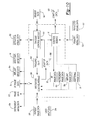
FIG. 9 is a simplified block diagram illustrating the navigation system of FIG. 8;
FIG. 10 is a dataflow diagram that illustrates a control system performed by a control module associated with the navigation system of FIG. 8;
FIG. 11 is an exemplary flowchart diagram that illustrates one of various control methods performed by the control module of FIG. 10;
FIG. 12 is an exemplary flowchart diagram that illustrates one of various control methods performed by the control module of FIG. 10; and
FIG. 13 is an exemplary flowchart diagram that illustrates one of various control methods performed by the control module of FIG. 10.
DETAILED DESCRIPTION
The following description is merely exemplary in nature and is not intended to limit the present disclosure, application, or uses. It should be understood that throughout the drawings, corresponding reference numerals indicate like or corresponding parts and features. As indicated above, the present teachings are directed toward providing a system and method for a radio-frequency (RF) imaging assisted medical procedure. Exemplary medical procedures can include diagnostic procedures, surgical procedures, etc. It should be noted, however, that the present teachings could be applicable to any appropriate procedure in which it is desirable to determine a position of an object within an anatomy, for example. Further, as used herein, the term module can refer to an application specific integrated circuit (ASIC), an electronic circuit, a processor (shared, dedicated, or group) and memory that executes one or more software or firmware programs, a combinational logic circuit, and/or other suitable software, firmware programs or components that provide the described functionality. Therefore, it will be understood that the following discussions are not intended to limit the scope of the appended claims.
As will be discussed further herein, a navigation system can comprise a RF imaging system 12. The RF imaging system 12 can be used solely or in combination with a second imaging device, as will be discussed. In addition, as will be discussed, the RF imaging system 12 can also be used solely or in combination with a tracking system, such as an electromagnetic tracking system. The use of a RF imaging system 12 can provide for non-contact imaging of anatomy, and further, the use of the RF imaging system 12 does not expose the patient or users to ionizing radiation. As will be discussed, the RF imaging system 12 can also allow for the imaging of boundaries within an anatomy, such as a boundary between bone and soft tissue.
RF Imaging System
With reference to FIG. 1, the RF imaging system 12 can include an imaging head 18, which can be in communication with a workstation 24. In one example, the imaging head 18 can comprise a radio-frequency imaging head, which can include a reflective, transmissive, and/or scattering radio-frequency based measurement system. Generally, the imaging head 18 can transmit and receive signals within a field of view F. The imaging head 18 can be used in cooperation with the workstation 24 to determine the types of material(s) encountered for a particular depth within the field of view F, and to display a graphical representation of the material(s) as the material(s) are arranged within the field of view F. Generally, the imaging head 18 can be used to determine the presence of instruments, people (e.g. physician, patient), implants, fiducials, operating equipment, etc. that are within the field of view F of the imaging head 18, as will be discussed in greater detail herein.
A suitable imaging head 18 can comprise at least one transmitter, at least one receiver, etc., as will be discussed in greater detail herein. A suitable transmitter can comprise at least one antenna capable of transmitting radio-frequency (RF) energy. A suitable receiver can comprise at least one antenna capable of receiving radio-frequency energy. Antennas suitable for transmitting and receiving suitable energy are commercially available from Next RF, Inc. of Huntsville, Ala. A suitable imaging head 18 can also comprise a combination of multiple receiving and one or more transmitting antennas assembled into an array. Using algorithms in the known art, such as the algorithms discussed in U.S. Pat. No. 4,123,759 to Hines et. al., incorporated herein by reference, energy can be divided among the transmitting antennas to focus and/or steer energy transmitted by the antennas into particular spatial regions for the purposes of isolating any return signals. These algorithms may be implemented in a variety of ways, including but not limited to electrical hardware design, software control, or mechanical means. Further, using algorithms in the known art, such as those disclosed in U.S. Pat. No. 7,068,981 to Sim, incorporated herein by reference, energy received by the receiving antennas can be processed to focus and assign this energy to isolate signals from particular spatial regions.
As the imaging head 18 can be commercially available, the imaging head 18 will not be discussed in further detail herein. In one example, the imaging head 18 can include at least one radio-frequency (RF) transmitter 20 and at least one radio-frequency (RF) receiver 22, which can be integrated into a single radio-frequency (RF) sensor or antenna, for example.
Generally, the RF transmitter 20 can emit or transmit RF energy signals in a variety of forms, for example but not limited to: pulses, frequency chirps, single frequencies, continuous waves, and various signal compositions and modulations. These signals can occupy various frequency ranges, such as microwave wavelengths, which can range from about 1 centimeter to about 1 meter. In particular, pulses from the RF transmitter 20 can be transmitted at various bandwidths and pulse repetition frequencies (PRF), such as a bandwidth from 0.01 gigahertz to about 10 gigahertz, and PRF of 20-100 megahertz.
Typically, at least a portion of the energy transmitted by the RF transmitter 20 can be reflected from interfaces between materials with different electrical properties within the field of view F of the imaging head 18 and a portion of the reflected energy or the reflected signal can be received by the RF receiver 22. Generally, the round-trip time-of-flight of the RF signal from the transmitter to the receiver is determined by the distance traveled by the signal and the electrical properties of the material(s) passed through. In addition, the shape of returned signals can be affected by the electrical properties and geometric configuration of the material(s) passed through. In one example, with reference to Table 1, exemplary electrical properties of potential target materials are provided:
TABLE 1
Electrical Properties of Various Portions of the Anatomy
Saline Blood Muscle/Skin
Relative Wavelength Relative Wavelength Relative Wavelength
Frequency Wavelength Dielectric in Tissue Dielectric in Tissue Dielectric in Tissue
MHz (cm) constant Conductivity (cm) Constant Conductivity (cm) constant Conductivity (cm)
433 69.3 70 1.72 7.5 62 1.2 8.2 53 1.43 8.5
915 32.8 70 1.8 3.8 60 1.4 4.1 51 1.6 4.4
2450 12.3 69 3.35 1.5 58 2.13 1.6 49 2.21 1.8
5800 5.2 63 6.42 0.6 51 5.33 0.7 43 4.73 0.8
10000 3 53 17.2 0.4 45 11.7 0.4 40 10.3 0.5
Lung Fat/Bone
Relative Wavelength Relative Wavelength
Frequency Wavelength Dielectric in Tissue Dielectric in Tissue
MHz (cm) Constant Conductivity (cm) Constant Conductivity (cm)
433 69.3 36  0.72 10.8 5.6 0.08 28.2
915 32.8 35  0.73 5.4 5.6 1 13.7
2450 12.3 32* 1.32* 2.2 5.5 16 5.2
5800 5.2 28* 4.07* 1 5.1 0.26 2.3
10000 3 25* 9.08* 0.6 4.5 0.44 1.4
*= extrapolated value
For further detail regarding the data illustrated in Table 1, see Lin, J. C., 1986: Microwave propagation in biological dielectrics with application to cardiopulmonary interrogation. In Medical Applications of Microwave Imaging Ed by L. E. Larsen and J. H. Jacobi, IEEE Press, NY, pp. 47-58, each incorporated by reference herein.
With continued reference to FIG. 1, the workstation 24 can be in communication with the RF transmitter 20 and the RF receiver 22 to determine the location of interfaces or boundaries between and electrical properties of material(s) encountered by the RF signal(s). The workstation 24 can include a display 26, a user input device 28 and a control module 30. The workstation 24 can also include or be connected to an image processor, navigation processor, and memory to hold instruction and data. The workstation 24 can provide facilities for displaying RF image data 32 on the display 26, saving, digitally manipulating, or printing a hard copy image of the received RF image data 32.
The user input device 28 can comprise any device that can enable a user to interface with the workstation 24, such as a touchpad, touch pen, touch screen, keyboard, mouse, voice-activated wireless mouse, or a combination thereof. The user input device 28 allows a physician or user 34 can also provide inputs to control the imaging head 18 or adjust the display settings of the display 26.
The control module 30 can output RF image data 32 to the display 26. The RF image data 32 can include a graphical representation of the boundaries and types of material(s) encountered by the RF signal, which can be displayed as the RF image data 32 on the display 26. In one example, the RF image data 32 can comprise at least one boundary, shaded area, icon, etc., which can denote the material(s) traversed by the signal, as illustrated in FIG. 1A.
Aggregating data from one or more signals, based on the return time for the signal(s), the shape or other characteristics of the return signal(s), the known shape of the transmitted signal(s), the known locations of the transmitter(s) and receiver(s), the known electrical properties of each material and optionally a model for expected spatial relationships among the material(s), the workstation 24 can determine the type and location of material(s) encountered by the signal.
The locations of the transmitter(s) and receiver(s) can be determined using a variety of means, including but not limited to: manufacturing specification, static measurement such as using direct physical measurement, manipulation with a physical mechanism such as a rotation stage, and dynamic measurement for example using a tracking system such as an electro-magnetic tracking system, further discussed herein.
Exemplary material(s) encountered by the signal can comprise saline, blood, skin, muscle, cancerous tissue, lung tissue, fat tissue, bone, polymer, metal, metal alloy, etc. Once the workstation 24 has determined the type and location of material(s) encountered by the signal(s), the workstation 24 can generate the RF image data 32 for display on the display 26.
Models for expected spatial relationships among materials can include, but are not limited to, information such as: the expected layers to be encountered by the signal, expected orientations of interfaces, and information determined by alternative imaging means such as 3D computed tomography (CT) or magnetic resonance (MR) imaging.
After a first determination of type and location of the material(s) encountered by the RF signal(s), measurements from additional signals can be used to refine this information. These additional signals can have RF parameters which are different than the first signal(s).
In addition, since the electrical properties of materials can vary based on secondary attributes of the material, including for example, water content, disease state, or density, the workstation 24 can also determine the secondary attributes for the material(s) encountered by the RF signal. The workstation 24 can output this data as additional image data 36 for display on the display 26. The additional image data 36 can comprise a secondary attribute metric for the material(s) encountered by the signal, and can be superimposed on the RF image data 32, if desired.
Further, localized variation of the electrical properties of materials can lead to an observed texture within a region of the material(s) encountered by the RF signal. This texture can be analyzed to measure, identify and locate sub-structure(s), and additional secondary attributes of the material(s).
In addition, by comparing textures and boundaries from multiple collections of RF signals sharing a common sub-region, dynamic information, such as motion or change in location of material(s), structure(s) and sub-structure(s) can be measured. Based on this information, additional images can be generated which reflect this dynamic information or data. Further, this dynamic information can also be used to measure cyclic and acyclic temporal attributes. These attributes can include, but are not limited to: cardiac and pulmonary cycles, injection bolus tracking, tracking of fiducials, biomechanical kinematics, disease progression, and implant dynamics and wear. This information can be displayed to the user on the display, or used to generate additional images.
With reference to FIG. 1, in one example, the imaging head 18 can be suspended above an operating table 40. In this example, the imaging head 18 can detect the presence of at least the user 34, the patient 8, and the operating table 40. In addition, due to the known electrical properties of the anatomy, the imaging head 18 can detect the boundary between the skin S of the patient 8, and the bone B of the patient 8, which can be displayed on the display as the RF image data 32 (FIG. 1A). This can enable the user 34 to visualize the boundary between the skin S and the bone B in a non-invasive manner.
Further, the known electrical properties of the anatomy can allow the workstation 24 to determine if a tissue imaged by the imaging head 18 is healthy or unhealthy. In this regard, cancerous tissue or tumors can have dielectric properties that can be substantially distinct from the dielectric properties associated with healthy or non-cancerous tissues. Thus, the workstation 24 can be used to determine if unhealthy or cancerous tissue has been encountered by the signal of the imaging head 18, as shown in FIG. 1A.
In addition, with reference to FIG. 1, the imaging head 18 could also be used to determine the location of metal, metal alloys, polymeric or other various man-made materials in the path of the signal due to the known electrical properties of such materials. In one example, the imaging head 18 can be used to determine the position of an implant 38 and an instrument 43 within the field of view F of the imaging head 18. The implant 38 can comprise any suitable implant, such as a spinal implant, orthopedic implant, implantable cardiac device, drug delivery device, etc., which can generally be composed of a metal, metal alloy or material having a known electrical properties. Given the known electrical properties of the implant 38, and known RF parameters of the signal, the control module 30 can determine a position of the implant 38 within the field of view of the imaging head 18, which can be output to the display 26 as implant data 38 a. The implant data 38 a can be superimposed on the RF image data 32 on the display 26, if desired.
Similar to the implant 38, the position of the instrument 43 within the field of view F of the imaging head 18 can be determined by the workstation 24. In this regard, the instrument 43 can comprise any suitable instrument, such as a guide wire, arthroscopic system, cardiac lead, deep-brain stimulator (DBS) probe, impacter, stylet, reamer, driver, tap, drill, etc. Given the known electrical properties of the instrument 43 and the known RF parameters of the signal, the control module 30 can determine a position of the instrument 43 within the field of view F of the imaging system 18, which can be output as instrument data 43 a to the display 26. The instrument data 43 a can be superimposed on the RF image data 32 on the display 26, if desired.
In one of various examples, with reference to FIG. 2, the imaging head 18 could be configured to be received within at least a portion of the operating table 40. In this regard, the operating table 40 can include at least one recess 40 a, which can be configured to receive an imaging head 18 c. The recess 40 a can generally be defined about a perimeter of the operating table 40, so that the imaging head 18 c can be positioned directly underneath at least a portion of the patient 8.
In one example, the imaging head 18 c can be sized to fit within the recess 40 a so that the imaging head 18 c is positioned under a substantial portion of the patient 8. Thus, in this example, the imaging head 18 c can substantially encompass an entire surface 40 b of the operating table 40. In other words, the imaging head 18 c can have a length L, which can be about equal to a length L1 of the operating table 40. This can enable the user 34 to visualize the anatomy of the patient 8 disposed over the length L of the imaging head 18 c, without requiring the use of ionizing radiation.
In another of various examples, as also illustrated in FIG. 2, an imaging head 18 d can cooperate with a non-imaging insert 42 to form the surface 40 of the operating table 40. In this example, the imaging head 18 d can have a length L2, which can be about half the length L1 of the operating table 40. The non-imaging insert 42 can have a length L3, which can be about half the length L1 of the operating table 40, so that the imaging head 18 d and the non-imaging insert 42 can be received with in the recess 40 a to form a surface of the operating table 40. In this example, the imaging head 18 d can be positioned under a selected portion of the anatomy, which can generally be the portion of the anatomy subjected to the surgical procedure. In one example, the imaging head 18 d can be positioned beneath a skull of a patient for imaging during a neurosurgical procedure. In another example, the imaging head 18 d can be positioned beneath the legs of a patient for imaging during a knee replacement procedure. In both of the above examples, the non-imaging insert 42 can be positioned within the recess 40 a opposite the imaging head 18 d to form a uniform surface for the operating table 40.
With reference to FIG. 3, in another of various examples, an imaging head 18 e can be coupled to a movable frame 44. The movable frame 44 can also support a workstation 24 e and a display 26 e. The movable frame 44 can include a body 44 a, an arm 44 b and one or more movable members 44 c. The body 44 a can support and couple the imaging head 18 e to the movable frame 44. The imaging head 18 e can be coupled to the body 44 a via any suitable technique, such as mechanical fasteners, press-fitting, etc. In addition, the imaging head 18 e could be integrally formed with the body 44 a, if desired.
The arm 44 b can support the workstation 24 e and display 26 e. In this example, the workstation 24 e could be located within a portion of the display 26 e, however, the workstation 24 e could be a separate unit, which could also be supported on the movable frame 44, via any suitable mechanism. The display 26 e can be movable or rotatable about the arm 44 b, so that the display 26 e can be moved into a desired viewing position.
The movable members 44 c can be coupled to the body 44 a. The movable members 44 c can comprise casters, rollers, wheels, etc. The movable members 44 c can allow the movable frame 44 to be portable so that the movable frame 44 can be moved for use in various areas of a hospital, for example. Thus, the movable frame 44 can allow the imaging head 18 e to comprise a portable imaging unit, which can be transported to various areas within a hospital, doctor's office, etc. to maximize the use of the imaging head 18 e.
With reference to FIG. 4, in one of various examples, an imaging head 18 f can be handheld. In this regard, the imaging head 18 f can be coupled to a graspable portion or handle 50, which can be sized to enable an operator to manipulate the imaging head 18 f with his/her hand. In one example, the RF transmitter 20 and the RF receiver 22 can be substantially contained within the handle 50. A cable 52 can enable wired communication between the imaging head 18 f and the workstation 24. It should be noted that the imaging head 18 f could be in wireless communication with the workstation 24, if desired.
With reference to FIG. 5, a simplified block diagram schematically illustrates an exemplary RF imaging system 12 for implementing the control module 30. The RF imaging system 12 can include the imaging head 18, which can include the RF transmitter 20 and the RF receiver 22. The RF imaging system 12 can also include the workstation 24 and the display 26. The workstation 24 can receive user input data 28 a. The user input data 28 a can be inputted by the user input device 28, and can comprise a signal to start the imaging process using the imaging head 18. Based on the receipt of the user input data 28 a, the workstation 24 can transmit a start-up signal 100 to the RF transmitter 20.
Based on the start-up signal 100, the RF transmitter 20 can emit RF energy in various ways, including in one or more signals with desired RF parameters, in the field of view F. The signal can be reflected from an object or material(s) within the field of view F, and the reflected signal can be received by the RF receiver 22. The RF receiver 22 can transmit reflected signal data 102 to the workstation 24. The reflected signal data 102 can comprise the signal reflected from the material(s).
The workstation 24 can be in communication with the RF receiver 22 to receive the reflected signal data 102, and can be in communication with the RF transmitter 20 to receive transmit signal data 104. The transmit signal data 104 can comprise an indication of the signal shape, transmitted frequency range, amplitude, and/or phase changes of transmitted RF signal. Based on the reflected signal data 102 and the transmit signal data 104, the workstation 24 can output the RF image data 32 for the display 26. The RF image data 32 can comprise a graphical representation of the material(s) encountered by the signals.
In addition, the workstation 24 can output the additional image data 36, the implant image data 38 a, and/or the instrument image data 43 a, which can be superimposed over the RF image data 32. As discussed, the additional image data 36 can comprise a graphical representation of the electrical properties of the material(s) encountered by the signals. The implant image data 38 a can comprise a graphical representation of the implant 38 within the field of view F of the imaging head 18, based on the material(s) encountered by the signals, and can comprise an icon of the implant 38, if desired. The instrument image data 43 a can comprise a graphical representation of the instrument 43 within the field of view F of the imaging head 18, based on the material(s) encountered by the signals, and can comprise an icon of the instrument 43, if desired.
With reference now to FIG. 6, a dataflow diagram illustrates an exemplary control system that can be embedded within the control module 30. Various embodiments of the navigation system according to the present disclosure can include any number of sub-modules embedded within the control module 30. The sub-modules shown may be combined and/or further partitioned to similarly determine the material(s) encountered by the RF signal(s), based on the transmit signal data 104 and the reflected signal data 102. In various embodiments, the control module 30 can be implemented by the workstation 24.
The control module 30 can receive as input the user input data 28 a, which can comprise a signal to activate the imaging head 18. Based on the user input data 28 a, the control module 30 can set start-up data 100 for the RF transmitter 20. The control module 30 can receive as input the transmit signal data 104 from the RF transmitter 20, and the reflected signal data 102 from the RF receiver 22. Given the transmit signal data 104 and the reflected signal data 102, the control module 30 can determine the material(s) encountered by the signal(s) emitted from the imaging head 18, and can output this data as RF image data 32. In addition, based on the transmit signal data 104 and the reflected signal data 102, the control module 30 can optionally determine the additional data, which can be output as additional image data 36. The control module 30 can also optionally determine if an implant 38 was encountered by the signal(s), and can output this data as the implant image data 38 a. Similarly, the control module 30 can optionally determine if an instrument 43 was encountered by the signal(s), and can output this data as the instrument image data 43 a.
With reference now to FIG. 7, a flowchart diagram illustrates an exemplary method performed by the control module 30. At block 200, the method can activate the RF transmitter 20 to transmit signals into the area defined by the field of view F. At block 202, the method can receive the signals reflected back from the material(s) encountered in the field of view F via the RF receiver 22. At block 204, the method can determine the time delay between the signals transmitted by the RF transmitter 20 and received by the RF receiver 22.
At block 206, the method can determine the boundary locations and electrical properties of the material(s) within the field of view F of the imaging head 18 based on the time delay, received signal shape, received frequency bands, amplitudes, and/or phase changes of the signals. At block 208, the method can determine the boundary locations and material(s) within the field of view F of the imaging head 18 based on the dielectric properties. At block 210, the method can output RF image data 32 to the display 26. At decision block 212, the method can determine if the procedure is complete. If the procedure is not complete, then the method can loop to block 200. Otherwise, the method can end.
Navigation System Including RF Imaging System
FIG. 8 is a diagram illustrating an overview of a navigation system 400 that can be used for various procedures. The navigation system 400 can be used in combination with the RF imaging system 12, and thus, the same reference numerals will be used to describe the same or similar items discussed with regard to FIGS. 1-7. In addition, since the RF imaging system 12 was discussed with regard to FIGS. 1-7, the RF imaging system 12 will not be discussed in great detail herein. Briefly, however, the RF imaging system 12 can be used in combination with or can be a component of the navigation system 400. The RF imaging system 12 can provide the navigation system 400 with RF image data 32, which can be used by the navigation system 400 to register the patient 8 to the image space, track one or more instruments 426 within the body, track one or more secondary imaging fiducials, and identify one or more instruments 426, as will be discussed herein.
In addition, the navigation system 400 can be used to determine the location of the transmitter(s) and receiver(s) comprising the imaging head 18. These measurements can then be used by the RF imaging system as inputs into the generation of the RF image data 32 by the workstation 24.
With continued reference to FIG. 8, the navigation system 400 can be used with the RF imaging system 12 to track the position and orientation of various instruments. Also, the navigation system 400 can be used with the RF imaging system 12 to track the location of an implant, such as a spinal implant or orthopedic implant, relative to a patient 8. It should further be noted that the navigation system 400 can be used with the RF imaging system 12 to navigate any type of instrument, implant, or delivery system, including: guide wires, arthroscopic systems, cardiac leads, orthopedic implants, spinal implants, deep-brain stimulator (DBS) probes, etc. relative to an anatomy. Moreover, these instruments may be used to navigate or map any region of the body. The navigation system 400, RF imaging system 12 and the various instruments may be used in any appropriate procedure, such as one that is generally minimally invasive, arthroscopic, percutaneous, stereotactic, or an open procedure.
In one example, the navigation system 400 may include a first imaging system or the RF imaging system 12, as discussed with regard to FIGS. 1-7, and a second imaging system, such as an imaging device 402. The second imaging device 402 can be used to acquire pre-, intra-, or post-operative or real-time image data of the patient 8. In one example, the optional second imaging device 402 can be, for example, a fluoroscopic x-ray imaging device that may be configured as an O-arm™ or a C-arm 404 having an x-ray source 406, an x-ray receiving section 408, an optional calibration and tracking target 410 and optional radiation sensors 412. It will be understood, however, that the second imaging device 402 can be optional, and the patient image data can also be acquired using other imaging devices, such as those discussed further herein.
In operation, the second imaging device 402 generates x-rays from the x-ray source 406 that propagate through the patient 8 and calibration and/or tracking target 410, into the x-ray receiving section 408. This allows real-time visualization of the patient 8 and radio-opaque instruments in the cone of the X-rays. In the example of FIG. 8, a longitudinal axis 8 a of the patient 8 is substantially in line with a mechanical rotational axis 414 of the C-arm 404. This can enable the C-arm 404 to be rotated relative to the patient 8, allowing images of the patient 8 to be taken from multiple directions or about multiple planes. An example of a fluoroscopic C-arm X-ray device that may be used as the optional second imaging device 402 is the “Series 9600 Mobile Digital Imaging System,” from GE Healthcare, (formerly OEC Medical Systems, Inc.) of Salt Lake City, Utah. Other exemplary fluoroscopes include bi-plane fluoroscopic systems, ceiling fluoroscopic systems, cath-lab fluoroscopic systems, fixed C-arm fluoroscopic systems, isocentric C-arm fluoroscopic systems, 3D fluoroscopic systems, etc. An exemplary O-arm™ imaging device is available from Medtronic Navigation, Inc. of Louisville, Colo.
When the x-ray source 406 generates the x-rays that propagate to the x-ray receiving section 408, the radiation sensors 412 can sense the presence of radiation, which is forwarded to an imaging device controller 420, to identify whether or not the second imaging device 402 is actively imaging. This information can also be transmitted to a coil array controller 422, further discussed herein.
The imaging device controller 420 can capture the x-ray images received at the x-ray receiving section 408 and store the images for later use. The leg that can be later used to follow contrast agent, such as Bolus tracking. The imaging device controller 420 may also be separate from the C-arm 404 and/or control the rotation of the C-arm 404. For example, the C-arm 404 can move in the direction of arrow A or rotate about the longitudinal axis 8 a of the patient 8, allowing anterior or lateral views of the patient 8 to be imaged. Each of these movements involves rotation about the mechanical axis 414 of the C-arm 404. The movements of the second imaging device 402, such as the C-arm 404 can be tracked with a tracking device 424.
While the optional second imaging device 402 is shown in FIG. 1 as a C-arm 404, any other alternative 2D, 3D or 4D imaging modality may also be used. For example, any 2D, 3D or 4D imaging device, such as an O-arm™ imaging device, isocentric fluoroscopy, bi-plane fluoroscopy, ultrasound, computed tomography (CT), multi-slice computed tomography (MSCT), magnetic resonance imaging (MRI), high frequency ultrasound (HFU), positron emission tomography (PET), optical coherence tomography (OCT), intra-vascular ultrasound (IVUS), ultrasound, intra-operative CT or MRI may also be used to acquire 2D, 3D or 4D pre- or post-operative and/or real-time images or patient image data 500 of the patient 8. For example, an intra-operative MRI system, may be used such as the PoleStar® MRI system sold by Medtronic, Inc.
It should further be noted that the second imaging device 402, as shown in FIG. 1, provides a virtual bi-plane image using a single-head C-arm fluoroscope as the second imaging device 402 by simply rotating the C-arm 404 about at least two planes, which could be orthogonal planes, to generate two-dimensional images that can be converted to three-dimensional volumetric images. By acquiring images in more than one plane, an icon 504 representing the location of an instrument 426, such as an impacter, stylet, reamer driver, taps, drill, deep-brain stimulator (DBS) probes, cardiac leads or other instrument, or implantable devices introduced and advanced in the patient 8, may be superimposed in more than one view and included in image data 502 displayed on the display 26, as will be discussed.
If the second imaging device 402 is employed, patient image data 500 can be forwarded from the imaging device controller 420 to a navigation computer and/or processor or workstation, such as the workstation 24. It will also be understood that the patient image data 500 is not necessarily first retained in the imaging device controller 420, but may also be directly transmitted to the workstation 24. The workstation 24 can include the display 26, the user input device 28 and a navigation control module 506. The workstation 24 can provide facilities for displaying the patient image data 500 as an image on the display 26, saving, digitally manipulating, or printing a hard copy image of the received patient image data 500.
The control module 506 can output image data 502 to the display 26. The image data 502 can include the icon 504 that provides an indication of a location of the instrument 426 with respect to the patient space, illustrated on the patient image data 500, as will be discussed herein. In addition, the image data 502 can include the RF image data 32, which can be superimposed on the patient image data 500.
With continuing reference to FIG. 8, the navigation system 400 can further include an optional electromagnetic navigation or tracking system 430. It should be noted that the tracking system 430 is optional, as the RF imaging system 12 can be used to track the position of instrument(s) 426 relative to the anatomy, if desired. If employed, the electromagnetic tracking system 430 can include a localizer, such as a first coil array 432 and/or second coil array 434, the coil array controller 422, a navigation probe interface 436, the device or instrument 426, a patient tracker or first reference frame or dynamic reference frame (DRF) 438 and one or more tracking devices 440. Other tracking systems can include an optical tracking system 430 a, for example the StealthStation® Treon® and the StealthStation® Tria® both sold by Medtronic Navigation, Inc. Further, other tracking systems can be used that include acoustic, radiation, infrared, etc., or hybrid systems, such as a system that includes components of both an electromagnetic and optical tracking system, etc. The instrument 426 and the DRF 438 can each include tracking device(s) 440.
The tracking device 440 or any appropriate tracking device as discussed herein, can include both a sensor, a transmitter, or combinations thereof and can be indicated by the reference numeral 440. Further, the tracking device 440 can be wired or wireless to provide a signal or emitter or receive a signal from a system. For example, a tracking device 440 can include one or more electromagnetic coils, such as a tri-axial coil, to sense a field produced by the localizing coil array 432 or 434. In another example, a tracking device 440 a can include or more optical receivers or transmitters for use with the optical tracking system 430 a. One will understand that the tracking device(s) 440 can receive a signal, transmit a signal, or combinations thereof to provide information to the navigation system 400, which can be used to determine a location of the tracking device 440. The navigation system 400 can determine a position of the instrument 426 and the DRF 438 based on the location of the tracking device(s) 440 to allow for accurate navigation relative to the patient 8 in the patient space.
In the case of an electromagnetic tracking system 430, the coil arrays 432, 434 can transmit signals that are received by the tracking device(s) 440. The tracking device(s) 440 can then transmit or receive signals based upon the transmitted or received signals from or to the coil arrays 432, 434. The coil arrays 432, 434 are shown attached to the operating table 40. It should be noted, however, that the coil arrays 432, 434 can also be positioned at any other location, as well and can also be positioned in the items being navigated. The coil arrays 432, 434 include a plurality of coils that are each operable to generate distinct electromagnetic fields into the navigation region of the patient 8, which is sometimes referred to as patient space. Representative electromagnetic systems are set forth in U.S. Pat. No. 5,913,820, entitled “Position Location System,” issued Jun. 22, 1999 and U.S. Pat. No. 5,592,939, entitled “Method and System for Navigating a Catheter Probe,” issued Jan. 14, 1997, each of which are hereby incorporated by reference. In addition, representative electromagnetic systems can include the AXIEM™ electromagnetic tracking system sold by Medtronic Navigation, Inc.
The coil arrays 432, 434 can be controlled or driven by the coil array controller 422. The coil array controller 422 can drive each coil in the coil arrays 432, 434 in a time division multiplex or a frequency division multiplex manner. In this regard, each coil can be driven separately at a distinct time or all of the coils can be driven simultaneously with each being driven by a different frequency. Upon driving the coils in the coil arrays 432, 434 with the coil array controller 422, electromagnetic fields are generated within the patient 8 in the area where the medical procedure is being performed, which is again sometimes referred to as patient space. The electromagnetic fields generated in the patient space induce currents in a tracking device(s) 440 positioned on or in the instrument 426, and DRF 438. These induced signals from the instrument 426 and DRF 438 are delivered to the navigation probe interface 436 and can be subsequently forwarded to the coil array controller 422.
In addition, the navigation system 400 can include a gating device or an ECG or electrocardiogram triggering device, which is attached to the patient 8, via skin electrodes, and in communication with the coil array controller 422. Respiration and cardiac motion can cause movement of cardiac structures relative to the instrument 426, even when the instrument 426 has not been moved. Therefore, patient image data 500 can be acquired from the second imaging device 402 based on a time-gated basis triggered by a physiological signal. For example, the ECG or EGM signal may be acquired from the skin electrodes or from a sensing electrode included on the instrument 426 or from a separate reference probe (not shown). A characteristic of this signal, such as an R-wave peak or P-wave peak associated with ventricular or atrial depolarization, respectively, may be used as a reference of a triggering event for the coil array controller 422 to drive the coils in the coil arrays 432, 434. This reference of a triggering event may also be used to gate or trigger image acquisition during the imaging phase with the second imaging device 402. By time-gating the image data 502 and/or the navigation data, the icon 504 of the location of the instrument 426 in image space relative to the patient space at the same point in the cardiac cycle may be displayed on the display 26. Further detail regarding the time-gating of the image data and/or navigation data can be found in U.S. Pub. Application No. 2004-00978906, entitled “Navigation System for Cardiac Therapies,” filed Nov. 19, 2002, which is hereby incorporated by reference.
The navigation probe interface 436 may provide the necessary electrical isolation for the navigation system 400. The navigation probe interface 436 can also include amplifiers, filters and buffers to directly interface with the tracking device(s) 440 in the instrument 426 and DRF 438. Alternatively, the tracking device(s) 440, or any other appropriate portion, may employ a wireless communications channel, such as that disclosed in U.S. Pat. No. 6,474,341, entitled “Surgical Communication Power System,” issued Nov. 5, 2002, herein incorporated by reference, as opposed to being coupled directly to the navigation probe interface 436.
The instrument 426 may be any appropriate instrument, such as an instrument for preparing a portion of the patient 8 or an instrument for positioning an implant. The DRF 438 of the tracking system 430 can be coupled to the navigation probe interface 436. The DRF 438 may be coupled to a first portion of the anatomical structure of the patient 8 adjacent to the region being navigated so that any movement of the patient 8 is detected as relative motion between the coil arrays 432, 434 and the DRF 438. For example, as will be discussed, the DRF 438 can be adhesively coupled to the patient 8, however, the DRF 438 could also be mechanically coupled to the patient 8, if desired. The DRF 438 may include any appropriate tracking device(s) 440 used by the navigation system 400. Therefore, the DRF 438 can include an optical tracking device or acoustic, etc. If the DRF 438 is used with an electromagnetic tracking device 440 a it can be configured as a pair of orthogonally oriented coils, each having the same centerline or may be configured in any other non-coaxial or co-axial coil configurations, such as a tri-axial coil configuration (not specifically shown).
Briefly, the navigation system 400 operates as follows. The navigation system 400 creates a translation map between all points in the radiological image generated from the second imaging device 402 in image space and the corresponding points in the anatomical structure of the patient 8 in patient space. After this map is established, whenever a tracked instrument, such as the instrument 426 is used, the workstation 24 in combination with the coil array controller 422 and the imaging device controller 420 uses the translation map to identify the corresponding point on the pre-acquired image or atlas model, which is displayed on display 26. This identification is known as navigation or localization. The icon 504 representing the localized point or instruments 426 can be shown as image data 502 on the display 26, along with the RF image data 32.
To enable navigation, the navigation system 400 must be able to detect both the position of the anatomical structure of the patient 8 and the position of the instrument 426. Knowing the location of these two items allows the navigation system 400 to compute and display the position of the instrument 426 in relation to the patient 8 on the display 26. The tracking system 430 can be employed to track the instrument 426 and the anatomical structure simultaneously, and optionally, the RF imaging system 12 can be employed with the tracking system 430 to track the instrument 426 and the anatomical structure, as will be discussed further herein.
The tracking system 430, if using an electromagnetic tracking assembly, essentially works by positioning the coil arrays 432, 434 adjacent to the patient space to generate a low-energy electromagnetic field generally referred to as a navigation field. Because every point in the navigation field or patient space is associated with a unique field strength, the tracking system 424 can determine the position of the instrument 426 by measuring the field strength at the tracking device 440 location. The DRF 438 can be fixed to the patient 8 to identify a first location of the patient 8 in the navigation field. The tracking system 424 can continuously recompute the relative position of the DRF 438 and the instrument 426 during localization and relate this spatial information to patient registration data to enable image guidance of the instrument 426 within and/or relative to the patient 8.
Patient registration is the process of determining how to correlate the position of the instrument 426 relative to the patient 8 to the position on the diagnostic or pre-acquired images. In one example, to register the patient 8, a physician or user 34 may use point registration by selecting and storing particular points from the pre-acquired images and then touching the corresponding points on the anatomical structure of the patient 8 with a pointer probe. The navigation system 400 analyzes the relationship between the two sets of points that are selected and computes a match, which correlates every point in the patient image data 500 with its corresponding point on the anatomical structure of the patient 8 or the patient space, as discussed herein. The points that are selected to perform registration are the fiducial markers 452, such as anatomical landmarks. Again, the landmarks or fiducial markers 452 are identifiable on the images, including RF images, and identifiable and accessible on the patient 8. The fiducial markers 452 can be artificial markers that are positioned on the patient 8 or anatomical landmarks that can be easily identified in the patient image data 500. The artificial landmarks can also form part of the DRF 438, such as those disclosed in U.S. Pat. No. 6,381,485, entitled “Registration of Human Anatomy Integrated for Electromagnetic Localization,” issued Apr. 30, 2002, herein incorporated by reference.
The navigation system 400 may also perform registration using anatomic surface information or path information as is known in the art. The navigation system 400 may also perform 2D to 3D registration by utilizing the acquired 2D images to register 3D volume images by use of contour algorithms, point algorithms or density comparison algorithms, as is known in the art. An exemplary 2D to 3D registration procedure, is set forth in U.S. Ser. No. 10/644,680, entitled “Method and Apparatus for Performing 2D to 3D Registration” filed on Aug. 20, 2003, hereby incorporated by reference.
In one of various examples, the RF imaging system 12 can also be used by the navigation system 400 to register the patient 8 to the image space. In this regard, as discussed, the imaging head 18 can be used to determine the location and material(s) encountered by the RF signal based on the electrical properties of the encountered material(s). This can enable the detection of anatomical landmarks that are non-palpable or not detectible with other sensors due to obstruction or other limitations. For example, in the case of a pelvis, layers of fat and the position of the patient 8 may make detection of anatomical landmarks difficult for image registration. Since the RF imaging system 12 can distinguish between fat and bone, the use of the RF imaging system 12 can improve image registration. In a further example, in the case of a skull of the patient 8, with reference to FIG. 1A, the skull can have a relatively smooth surface, which can result in few unique surface landmarks. Since the RF imaging system 12 can determine a boundary, thickness or depth of various boney tissues in the skull, such as the boundary between trabecular and cortical bone, the RF imaging system 12 can provide alternative landmarks for image registration.
In order to maintain registration accuracy, with reference to FIG. 8, the navigation system 400 and/or the RF imaging system 12 continuously tracks the position of the patient 8 during registration and navigation. This is because the patient 8, DRF 438 and coil arrays 432, 434 may all move with respect to one another during the procedure, even when this movement is not desired. Alternatively the patient 8 may be held immobile once the registration has occurred, such as with a head frame (not shown). Therefore, if the navigation system 400 did not track the position of the patient 8 or area of the anatomy, any patient movement after image acquisition would result in inaccurate navigation within that image.
The DRF 438 allows the tracking system 430 to register and track the anatomy. Because the DRF 438 can be coupled to the patient 8, any movement of the anatomical structure of the patient 8 or the coil arrays 432, 434 can be detected as the relative motion between the coil arrays 432, 434 and the DRF 438. Both the relative motion of the coil arrays 432, 434 and the DRF 438 can be communicated to the coil array controller 422, via the navigation probe interface 436, which can update the registration correlation to thereby maintain accurate navigation.
It should be noted, however, that the DRF 438 can be optional. In this regard, the RF imaging system 12 can be used to track the anatomical movement of the patient 8. As the RF imaging system 12 can determine the boundaries of the material(s) encountered, if the boundaries shift, the workstation 24 can determine that anatomical movement has occurred. Based on this determination, registration can be updated to maintain accurate navigation.
In addition, with continued reference to FIG. 8, the RF imaging system 12 can be used with the navigation system 400 to identify various instruments 426 within the patient space or field of view F of the imaging head 18. In this regard, each instrument 426 can include at least one identification tag visible to the RF imaging 426 a. The tag 426 a can enable the imaging head 18 to identify the instrument(s) 426 within the field of view F of the imaging head 18. For example, the tag 426 a can include a type of instrument 426, and in cases where the instrument 426 has interchangeable members, such as tips, a tag 426 a could be associated with each of the interchangeable members to identify which tip is coupled to the instrument 426. In addition, based on the data provided by the tag 426 a, the workstation 24 can also display a message on the display 26 if, for example, an interchangeable member is coupled to the wrong instrument 426. It should also be noted that devices, other than instruments 426, can include an tag. For example, staff, imaging systems, etc. can include tags to identify the objects to the workstation 24 via the imaging head 18.
Further, it should be noted that the imaging head 18 can be used in cooperation with the tracking system 430. In this regard, the imaging head 18 can include a tracking device 440 c, which can enable the tracking system 430 to determine the position of the imaging head 18 within the patient space. This can allow the RF image data 32 obtained from the imaging head 18 to be placed directly into the common three-dimensional context or coordinate system used with the other objects tracked by the tracking system 430, such as the DRF 438, instrument(s) 426, etc.
In addition, the use of the tracking device 440 c with the imaging head 18 can allow the registration of the RF image data 32 with tracking data obtained from the tracking system 430, and with other images, such as with the patient image data 500. In this regard, since the tracking system 430 is registered with the patient image data 500 in image space, and the position of the imaging head 18 can be determined by the tracking system 430, the images acquired by the imaging head 18 or RF image data 32, can be easily registered with the patient image data 500 in image space. This can enable the workstation 24 to provide the surgeon or user with a variety of different information regarding the patient 8.
It should also be noted that the RF imaging system 12 can be used with the navigation system 400 in place of or as a supplement to the tracking system 430. In this regard, the imaging head 18 can be used to track devices within the anatomy of the patient 8, such as implants 38 or instruments 426, as discussed with regard to FIGS. 1-7.
With reference to FIG. 9, a simplified block diagram schematically illustrates an exemplary navigation system 400 for implementing the navigation control module 506. The navigation system 400 can include the tracking system 430, the RF imaging system 12, the workstation 24 and the display 26. The tracking system 430 can comprise the electromagnetic tracking system 430 or the optical tracking system 430 b, and will generally be referred to as the tracking system 430. The RF imaging system 12 can include the RF transmitter 20 and the RF receiver 22. The workstation 24 can receive user input data 28 a from the user input device 28. The user input data 28 a can comprise a signal to start the navigated surgical procedure using at least one of the RF imaging system 12 and the tracking system 430. Based on the receipt of the user input data 28 a, the workstation 24 can transmit a start-up data 598 to the RF transmitter 20 and/or the tracking system 430.
Based on the start-up data 598, the RF transmitter 20 can emit one or more signals in the field of view F. The signals can be reflected from an object or material(s) within the field of view F, and the reflected signals can be received by the RF receiver 22. The RF receiver 22 can transmit reflected signal data 102 to the workstation 24. The reflected signal data 102 can comprise the signals reflected from the material(s) in the field of view F of the imaging head 18.
In addition, based on the start-up data 598, the tracking system 430 can set activation signal data 602. In the case of the electromagnetic tracking system 430, the activation signal data 602 can comprise a signal to activate the coil arrays 46, 47 to generate an electromagnetic field to which the tracking devices 440 coupled to the instrument 426, the DRF 438, etc. can respond.
When the tracking devices 440 are activated, the tracking devices 440 can transmit sensor data 604 indicative of a location of the tracking device 440 in the patient space to the tracking system 430. Based on the sensor data 604 received by the tracking system 430, the tracking system 430 can generate and set the tracking data 606 for the navigation control module 506. The tracking data 606 can include data regarding the coordinate locations (positions and orientations) of the objects coupled to the tracking devices 440, such as the instrument 426 and DRF 438, as computed from the sensor data 210.
The workstation 24 can be in communication with the RF receiver 22 to receive the reflected signal data 102, and can be in communication with the RF transmitter 20 to receive transmit signal data 104. The workstation 24 can also be in communication with the tracking system 430 to receive the tracking data 606. The workstation 24 can also receive patient image data 500 from the optional second imaging device 402. Based on the reflected signal data 102, the transmit signal data 104, the tracking data 606 and the patient image data 500, the workstation 24 can output the image data 502 and RF image data 32 for the display 26. The RF image data 32 can comprise a graphical representation of the material(s) encountered by the signals, which can be superimposed on the patient image data 500. In addition, as discussed with regard to FIG. 5, the workstation 24 can output the additional image data 36, the implant image data 38 a, and/or the instrument image data 43 a, which can be superimposed over the RF image data 32, the patient image data 500 and/or the image data 502.
With reference now to FIG. 10, a dataflow diagram illustrates an exemplary control system that can be embedded within the control module 506. Various embodiments of the navigation system according to the present disclosure can include any number of sub-modules embedded within the control module 506. The sub-modules shown may be combined and/or further partitioned to similarly facilitate a navigated surgical procedure, based on the transmit signal data 104, the reflected signal data 102 and/or the tracking data 606. In various embodiments, the control module 506 includes the tracking system 430, which can implement a tracking control module 600, and the workstation 24, which can implement the navigation control module 506 and the control module 30. It should be noted, however, that the tracking control module 600, the navigation control module 506 and the control module 30 could be implemented on the workstation 24, if desired.
The control module 30 can receive as input the user input data 28 a, which can comprise a signal to activate the imaging head 18. Based on the user input data 28 a, the control module 30 can set start-up data 598 for the RF transmitter 20. The control module 30 can receive as input the transmit signal data 104 from the RF transmitter 20, and the reflected signal data 102 from the RF receiver 22. Given the transmit signal data 104 and the reflected signal data 102, the control module 30 can determine the material(s) encountered by the signal(s) emitted from the imaging head 18, and can set this data as RF image data 32 for the navigation control module 506.
In addition, based on the transmit signal data 104 and the reflected signal data 102, the control module 30 can optionally determine the additional image data, which can be set as additional image data 36 for the navigation control module 506. The control module 30 can also optionally determine if an implant 38 is present in the field of view F of the imaging head 18, and can output this data as the implant image data 38 a for the navigation control module 506. Similarly, the control module 30 can optionally determine if an instrument 43 is present in the field of view F of the imaging head 18, and can output this data as the instrument image data 43 a for the navigation control module 506.
The tracking control module 600 can receive as input the start-up data 598 from the navigation control module 506 and sensor data 604 from the tracking device(s) 440. Upon receipt of the start-up data 598, the tracking control module 600 can output the activation signal data 602 for the tracking device(s) 440. Upon receipt of the sensor data 604, the tracking control module 600 can set the tracking data 606 for the navigation control module 506. As discussed, the tracking data 606 can include data regarding the coordinate locations (positions and orientations) of the objects coupled to the tracking device(s) 440, such as the instrument 426 and the DRF 438.
The navigation control module 506 can receive as input the RF image data 32, the user input data 28 a, the tracking data 606 and the patient image data 500. Optionally, the navigation control module 506 can receive as input the additional image data 36, the implant image data 38 a, and/or the instrument image data 43 a from the control module 30.
Based on the RF image data 32 and the tracking data 606, the navigation control module 506 can determine the appropriate patient image data 500 for display on the display 26, and can output both the tracking data 606 and the patient image data 100 as image data 102. The navigation control module 506 can also output the RF image data 32, which can be superimposed on the image data 102 or the patient image data 500.
With reference now to FIG. 11, a flowchart diagram illustrates an exemplary method performed by the navigation control module 506. At decision block 700, the method can determine if user input data 28 a has been received to activate the tracking system 430. If no user input data 28 a has been received, the method can go to decision block 702. At decision block 702, the method can determine if user input data 28 a has been received to activate the RF imaging system 12. If user input data 28 a has been received to activate the RF imaging system 12, then the method can go to B on FIG. 7. Otherwise, the method can loop to decision block 700.
If user input data 28 a has been received at decision block 600 to activate the tracking system 430, then the method can go to decision block 704. At decision block 704, the method can determine if user input data 28 a has been received to activate the RF imaging system 12. If user input data 28 a has been received to activate the RF imaging system 12, then the method can go to A on FIG. 13. Otherwise, the method can go to Con FIG. 12.
With reference to FIG. 12, at block 720, the method can transmit the activation signal data 602 to the tracking device(s) 440. At block 722, the method can receive sensor data 604 from the tracking device(s) 440. At block 724, the method can determine the position (location and orientation) of the objects coupled to the tracking device(s) 440, such as the instrument 426 and the DRF 438. Then, at block 726, the method can output image data 502, which can include the tracking data 606 superimposed on the patient image data 500. At decision block 728, the method can determine if the surgical procedure is complete. If the surgical procedure is complete, the method can end. Otherwise, the method can loop to block 720.
With reference to FIG. 13, at block 750, the method can transmit the activation signal data 602 to the tracking device(s) 440. At block 752, the method can activate the RF transmitter 20 to transmit signals into the area defined by the field of view F. At block 754, the method can receive sensor data 604 from the tracking device(s) 440. At block 756, the method can receive the signals reflected back from the material(s) encountered in the field of view F via the RF receiver 22. Then, at block 758, the method can determine the position (location and orientation) of the objects coupled to the tracking device(s) 440, such as the instrument 426 and the DRF 438. At block 760, the method can determine the time delay between the signals transmitted by the RF transmitter 20 and received by the RF receiver 22. Next, at block 762, the method can determine the electrical properties of the material(s) encounter by the signals based on the signal time delay and the known RF parameters of the signal. At block 764, the method can determine the material(s) encountered by the signals based on the electrical properties(s). Next, at block 766, the method can output the image data 502 and the RF image data 32. Note that the RF image data 502 can be superimposed on the image data 502 or the patient image data 500. At decision block 768, the method can determine if the procedure is complete. If the procedure is not complete, then the method can loop to block 750. Otherwise, the method can end.
While specific examples have been described in the specification and illustrated in the drawings, it will be understood by those of ordinary skill in the art that various changes may be made and equivalents may be substituted for elements thereof without departing from the scope of the present disclosure as defined in the claims. Furthermore, the mixing and matching of features, elements and/or functions between various examples is expressly contemplated herein so that one of ordinary skill in the art would appreciate from this disclosure that features, elements and/or functions of one example may be incorporated into another example as appropriate, unless described otherwise, above. Moreover, many modifications may be made to adapt a particular situation or material to the teachings of the present disclosure without departing from the essential scope thereof. Therefore, it is intended that the present disclosure not be limited to the particular examples illustrated by the drawings and described in the specification as the best mode presently contemplated for carrying out this disclosure, but that the scope of the present disclosure will include any embodiments falling within the foregoing description and the appended claims.

Claims (30)

What is claimed is:
1. A system for performing a medical procedure with at least one instrument on a patient comprising:
an imaging head defining a field of view relative to the patient, the imaging head including:
at least one radio-frequency transmitter that emits a least one signal in the field of view;
at least one radio-frequency receiver that receives a plurality of reflected radio frequency signals based on at least one electrical property of at least one material in the field of view and the at least one instrument;
a workstation having a control module that determines, based on the plurality of reflected radio frequency signals received by the at least one radio-frequency receiver, a location of at least one boundary of the at least one material within the field of view and a location of the at least one instrument in relation to the patient in the field of view;
wherein the workstation is configured to determine a type of material associated with the at least one instrument based upon the reflected radio frequency signals associated with the at least one instrument and a signal produced by the at least one radio-frequency transmitter; and
a display that displays an image of the location of the at least one boundary, and renders an icon of the at least one instrument on the image.
2. The system of claim 1, wherein the at least one material within the field of view is selected from at least one of the group comprising: skin, muscle tissue, grey matter, nerve tissue, bone tissue, cancerous tissue, noncancerous tissue, fatty tissue, lung tissue, blood, saline, polymer, metal, metal alloy and combinations thereof.
3. The system of claim 1, wherein the workstation is integral with the imaging head.
4. The system of claim 1, wherein the imaging head is coupled to at least a portion of an operating table.
5. The system of claim 1, wherein the imaging head is coupled to at least a portion of a wall of an operating room.
6. The system of claim 1, wherein the imaging head is movable relative to the patient.
7. The system of claim 6, wherein the imaging head is handheld.
8. The system of claim 1, wherein the imaging head is fixed relative to the patient.
9. The system according to claim 1, wherein the workstation is configured to track movement of the at least one boundary.
10. The system according to claim 9, wherein the workstation is configured to determine an amount of anatomical movement based on movement of the at least one boundary.
11. The system according to claim 10, further comprising a navigation system having a tracking device attached to the imaging head to track the location of the imaging head, wherein the navigation system is configured to update a registration of the image relative to the patient location based on the movement of the at least one boundary.
12. The system according to claim 1, wherein the work station is configured to determine a type of instrument associated with the at least one material.
13. A system for performing a medical procedure on a patient comprising:
at least one tracking device;
a tracking system that tracks the at least one tracking device;
an imaging head having an imaging system that transmits at least one imaging radio-frequency signal within a field of view and receives at least one reflected imaging radio-frequency signal within the field of view for forming an image, the imaging head having at least one transmitter that emits the at least one imaging radio-frequency signal in the field of view, wherein the imaging head has at least one receiver that receives the at least one reflected imaging radio-frequency signal; and
a navigation system that determines, based on the tracking of the tracking device and RF image data formed from the at least one reflected imaging radio-frequency signal, a location of the imaging head, the at least one tracking device and the patient during registration and navigation, within the field of view.
14. The system of claim 13, wherein the at least one tracking device is coupled to an instrument, an implant, the imaging head, the patient, or combinations thereof.
15. The system according to claim 13, wherein the imaging head is configured to superimpose RF image data with patient image data.
16. The system according to claim 13, wherein the imaging system determines, based on the at least one reflected radio-frequency signal a type of instrument associated with the at least one instrument based upon a material associated with the at least one instrument.
17. The system of claim 13, wherein the at least one reflected radio-frequency signal received by the at least one receiver is based on at least one electrical property associated with at least one material in the field of view.
18. The system of claim 17, wherein the navigation system determines, based on the at least one reflected imaging radio-frequency signal received by the at least one receiver, a location of at least one boundary of at least one material within the field of view.
19. The system of claim 18, further comprising:
a display that displays an image of the location of the at least one boundary of the at least one material and the location of the at least one tracking device relative to the at least one boundary.
20. The system of claim 18, wherein the at least one material within the field of view is selected from at least one of the group comprising: skin, muscle tissue, grey matter, nerve tissue, bone tissue, cancerous tissue, noncancerous tissue, fatty tissue, lung tissue, blood, saline, polymer, metal, metal alloy and combinations thereof.
21. The system according to claim 18, wherein the navigation system is configured to track movement of the at least one boundary.
22. The system according to claim 21, wherein the navigation system is configured to determine an amount of anatomical movement based on movement of the at least one boundary.
23. The system according to claim 22, wherein the navigation system is configured to update a registration of the image relative to the patient location based on the movement of the at least one boundary.
24. A method for performing a medical procedure on a patient comprising:
positioning at least one imaging head relative to a patient to define a field of view;
positioning at least one surgical instrument relative to a patient in the field of view;
emitting at least one radio-frequency signal from the imaging head into the field of view;
receiving a plurality of reflected radio-frequency signals from the field of view with the imaging head;
determining, based on the plurality of reflected radio-frequency signals received from the field of view, at least one electrical property associated with at least one material and the at least one instrument within the field of view;
determining, based on the at least one electrical property and the plurality of reflected radio-frequency signals received from the field of view, a location of a boundary associated with the at least one material within the field of view and the location of the at least one surgical instrument; and
determining a type of instrument associated with the at least one instrument based upon a material associated with the at least one instrument and the plurality of reflected radio-frequency signals.
25. The method of claim 24, further comprising:
displaying a graphical representation of the location of the boundary and the at least one material on a display.
26. The method of claim 24, wherein determining the at least one electrical property associated with the at least one material further comprises:
determining if the at least one material within the field of view is from at least one of the group comprising: skin, muscle tissue, grey matter, nerve tissue, bone tissue, cancerous tissue, noncancerous tissue, fatty tissue, lung tissue, blood, saline, polymer, metal, metal alloy or combinations thereof.
27. The method of claim 24, further comprising:
tracking at least one tracking device; and
determining, based on the tracking of the at least one tracking device, a location of the at least one tracking device relative to the boundary associated with the at least one material within the field of view.
28. The method according to claim 27, further comprising rendering an icon of the at least one instrument on an image.
29. The method according to claim 24, further including determining a type of instrument associated with the at least one instrument based upon an identification tag associated with the at least one instrument and the plurality reflected radio-frequency signals.
30. The method according to claim 24, further including determining if the boundary has moved, thus indicating an anatomical movement.
US12/767,449 2010-04-26 2010-04-26 System and method for radio-frequency imaging, registration, and localization Active 2031-08-25 US8717430B2 (en)

Priority Applications (4)

Application Number Priority Date Filing Date Title
US12/767,449 US8717430B2 (en) 2010-04-26 2010-04-26 System and method for radio-frequency imaging, registration, and localization
PCT/US2011/033108 WO2011136986A1 (en) 2010-04-26 2011-04-19 System and method for radio-frequency imaging, registration and localization
EP11718816.9A EP2563259B1 (en) 2010-04-26 2011-04-19 System and method for radio-frequency imaging, registration and localization
US14/269,799 US10939053B2 (en) 2010-04-26 2014-05-05 System and method for radio-frequency imaging, registration, and localization

Applications Claiming Priority (1)

Application Number Priority Date Filing Date Title
US12/767,449 US8717430B2 (en) 2010-04-26 2010-04-26 System and method for radio-frequency imaging, registration, and localization

Related Child Applications (1)

Application Number Title Priority Date Filing Date
US14/269,799 Continuation US10939053B2 (en) 2010-04-26 2014-05-05 System and method for radio-frequency imaging, registration, and localization

Publications (2)

Publication Number Publication Date
US20110261180A1 US20110261180A1 (en) 2011-10-27
US8717430B2 true US8717430B2 (en) 2014-05-06

Family

ID=44121008

Family Applications (2)

Application Number Title Priority Date Filing Date
US12/767,449 Active 2031-08-25 US8717430B2 (en) 2010-04-26 2010-04-26 System and method for radio-frequency imaging, registration, and localization
US14/269,799 Active 2033-01-05 US10939053B2 (en) 2010-04-26 2014-05-05 System and method for radio-frequency imaging, registration, and localization

Family Applications After (1)

Application Number Title Priority Date Filing Date
US14/269,799 Active 2033-01-05 US10939053B2 (en) 2010-04-26 2014-05-05 System and method for radio-frequency imaging, registration, and localization

Country Status (3)

Country Link
US (2) US8717430B2 (en)
EP (1) EP2563259B1 (en)
WO (1) WO2011136986A1 (en)

Cited By (101)

* Cited by examiner, † Cited by third party
Publication number Priority date Publication date Assignee Title
US9078685B2 (en) 2007-02-16 2015-07-14 Globus Medical, Inc. Method and system for performing invasive medical procedures using a surgical robot
US20170172665A1 (en) * 2013-12-31 2017-06-22 Mako Surgical Corp. Systems and methods for generating customized control boundaries
US9782229B2 (en) 2007-02-16 2017-10-10 Globus Medical, Inc. Surgical robot platform
US10080615B2 (en) 2015-08-12 2018-09-25 Globus Medical, Inc. Devices and methods for temporary mounting of parts to bone
US10117632B2 (en) 2016-02-03 2018-11-06 Globus Medical, Inc. Portable medical imaging system with beam scanning collimator
US10136954B2 (en) 2012-06-21 2018-11-27 Globus Medical, Inc. Surgical tool systems and method
US10231791B2 (en) 2012-06-21 2019-03-19 Globus Medical, Inc. Infrared signal based position recognition system for use with a robot-assisted surgery
US10292778B2 (en) 2014-04-24 2019-05-21 Globus Medical, Inc. Surgical instrument holder for use with a robotic surgical system
US10357184B2 (en) 2012-06-21 2019-07-23 Globus Medical, Inc. Surgical tool systems and method
US10448910B2 (en) 2016-02-03 2019-10-22 Globus Medical, Inc. Portable medical imaging system
US10470809B1 (en) 2018-06-19 2019-11-12 Summate Technologies, Inc. Automated screw identification system and method
US10569794B2 (en) 2015-10-13 2020-02-25 Globus Medical, Inc. Stabilizer wheel assembly and methods of use
US10573023B2 (en) 2018-04-09 2020-02-25 Globus Medical, Inc. Predictive visualization of medical imaging scanner component movement
US10580217B2 (en) 2015-02-03 2020-03-03 Globus Medical, Inc. Surgeon head-mounted display apparatuses
US10646283B2 (en) 2018-02-19 2020-05-12 Globus Medical Inc. Augmented reality navigation systems for use with robotic surgical systems and methods of their use
US10660712B2 (en) 2011-04-01 2020-05-26 Globus Medical Inc. Robotic system and method for spinal and other surgeries
US10671969B2 (en) 2017-05-03 2020-06-02 Summate Technologies, Inc. Operating room situated, parts-inventory control system and supervisory arrangement for accurately tracking the use of and accounting for the ultimate disposition of an individual component part of a complete implant which is then being surgically engrafted in-vivo upon or into the body of a living subject
US10675094B2 (en) 2017-07-21 2020-06-09 Globus Medical Inc. Robot surgical platform
US10813704B2 (en) 2013-10-04 2020-10-27 Kb Medical, Sa Apparatus and systems for precise guidance of surgical tools
US10842453B2 (en) 2016-02-03 2020-11-24 Globus Medical, Inc. Portable medical imaging system
US10866119B2 (en) 2016-03-14 2020-12-15 Globus Medical, Inc. Metal detector for detecting insertion of a surgical device into a hollow tube
US10893912B2 (en) 2006-02-16 2021-01-19 Globus Medical Inc. Surgical tool systems and methods
US10898252B2 (en) 2017-11-09 2021-01-26 Globus Medical, Inc. Surgical robotic systems for bending surgical rods, and related methods and devices
US10909343B1 (en) 2019-07-12 2021-02-02 Summate Technologies, Inc. Automated screw identification system and method with labeled pegs
US10925681B2 (en) 2015-07-31 2021-02-23 Globus Medical Inc. Robot arm and methods of use
US10939053B2 (en) 2010-04-26 2021-03-02 Medtronic Navigation, Inc. System and method for radio-frequency imaging, registration, and localization
US10939968B2 (en) 2014-02-11 2021-03-09 Globus Medical Inc. Sterile handle for controlling a robotic surgical system from a sterile field
US10945742B2 (en) 2014-07-14 2021-03-16 Globus Medical Inc. Anti-skid surgical instrument for use in preparing holes in bone tissue
US10973594B2 (en) 2015-09-14 2021-04-13 Globus Medical, Inc. Surgical robotic systems and methods thereof
US11026752B2 (en) 2018-06-04 2021-06-08 Medtronic Navigation, Inc. System and method for performing and evaluating a procedure
US11045267B2 (en) 2012-06-21 2021-06-29 Globus Medical, Inc. Surgical robotic automation with tracking markers
US11045179B2 (en) 2019-05-20 2021-06-29 Global Medical Inc Robot-mounted retractor system
US11058378B2 (en) 2016-02-03 2021-07-13 Globus Medical, Inc. Portable medical imaging system
US11109922B2 (en) 2012-06-21 2021-09-07 Globus Medical, Inc. Surgical tool systems and method
US11116576B2 (en) 2012-06-21 2021-09-14 Globus Medical Inc. Dynamic reference arrays and methods of use
US11134862B2 (en) 2017-11-10 2021-10-05 Globus Medical, Inc. Methods of selecting surgical implants and related devices
US11153555B1 (en) 2020-05-08 2021-10-19 Globus Medical Inc. Extended reality headset camera system for computer assisted navigation in surgery
US11207150B2 (en) 2020-02-19 2021-12-28 Globus Medical, Inc. Displaying a virtual model of a planned instrument attachment to ensure correct selection of physical instrument attachment
US11253216B2 (en) 2020-04-28 2022-02-22 Globus Medical Inc. Fixtures for fluoroscopic imaging systems and related navigation systems and methods
US11253327B2 (en) 2012-06-21 2022-02-22 Globus Medical, Inc. Systems and methods for automatically changing an end-effector on a surgical robot
US11266470B2 (en) 2015-02-18 2022-03-08 KB Medical SA Systems and methods for performing minimally invasive spinal surgery with a robotic surgical system using a percutaneous technique
US11273283B2 (en) 2017-12-31 2022-03-15 Neuroenhancement Lab, LLC Method and apparatus for neuroenhancement to enhance emotional response
US11278360B2 (en) 2018-11-16 2022-03-22 Globus Medical, Inc. End-effectors for surgical robotic systems having sealed optical components
US11298196B2 (en) 2012-06-21 2022-04-12 Globus Medical Inc. Surgical robotic automation with tracking markers and controlled tool advancement
US11317971B2 (en) 2012-06-21 2022-05-03 Globus Medical, Inc. Systems and methods related to robotic guidance in surgery
US11317973B2 (en) 2020-06-09 2022-05-03 Globus Medical, Inc. Camera tracking bar for computer assisted navigation during surgery
US11317978B2 (en) 2019-03-22 2022-05-03 Globus Medical, Inc. System for neuronavigation registration and robotic trajectory guidance, robotic surgery, and related methods and devices
US11337769B2 (en) 2015-07-31 2022-05-24 Globus Medical, Inc. Robot arm and methods of use
US11337742B2 (en) 2018-11-05 2022-05-24 Globus Medical Inc Compliant orthopedic driver
US11351007B1 (en) 2018-01-22 2022-06-07 CAIRA Surgical Surgical systems with intra-operative 3D scanners and surgical methods using the same
US11357548B2 (en) 2017-11-09 2022-06-14 Globus Medical, Inc. Robotic rod benders and related mechanical and motor housings
US11364361B2 (en) 2018-04-20 2022-06-21 Neuroenhancement Lab, LLC System and method for inducing sleep by transplanting mental states
US11382713B2 (en) 2020-06-16 2022-07-12 Globus Medical, Inc. Navigated surgical system with eye to XR headset display calibration
US11382549B2 (en) 2019-03-22 2022-07-12 Globus Medical, Inc. System for neuronavigation registration and robotic trajectory guidance, and related methods and devices
US11382700B2 (en) 2020-05-08 2022-07-12 Globus Medical Inc. Extended reality headset tool tracking and control
US11382699B2 (en) 2020-02-10 2022-07-12 Globus Medical Inc. Extended reality visualization of optical tool tracking volume for computer assisted navigation in surgery
US11395706B2 (en) 2012-06-21 2022-07-26 Globus Medical Inc. Surgical robot platform
US11399900B2 (en) 2012-06-21 2022-08-02 Globus Medical, Inc. Robotic systems providing co-registration using natural fiducials and related methods
US11419616B2 (en) 2019-03-22 2022-08-23 Globus Medical, Inc. System for neuronavigation registration and robotic trajectory guidance, robotic surgery, and related methods and devices
US11426178B2 (en) 2019-09-27 2022-08-30 Globus Medical Inc. Systems and methods for navigating a pin guide driver
US11432882B2 (en) 2019-09-17 2022-09-06 CAIRA Surgical System and method for medical object tracking
US11439444B1 (en) 2021-07-22 2022-09-13 Globus Medical, Inc. Screw tower and rod reduction tool
US11452839B2 (en) 2018-09-14 2022-09-27 Neuroenhancement Lab, LLC System and method of improving sleep
US11510750B2 (en) 2020-05-08 2022-11-29 Globus Medical, Inc. Leveraging two-dimensional digital imaging and communication in medicine imagery in three-dimensional extended reality applications
US11510684B2 (en) 2019-10-14 2022-11-29 Globus Medical, Inc. Rotary motion passive end effector for surgical robots in orthopedic surgeries
US11523785B2 (en) 2020-09-24 2022-12-13 Globus Medical, Inc. Increased cone beam computed tomography volume length without requiring stitching or longitudinal C-arm movement
US11529195B2 (en) 2017-01-18 2022-12-20 Globus Medical Inc. Robotic navigation of robotic surgical systems
US11571265B2 (en) 2019-03-22 2023-02-07 Globus Medical Inc. System for neuronavigation registration and robotic trajectory guidance, robotic surgery, and related methods and devices
US11571171B2 (en) 2019-09-24 2023-02-07 Globus Medical, Inc. Compound curve cable chain
US11602402B2 (en) 2018-12-04 2023-03-14 Globus Medical, Inc. Drill guide fixtures, cranial insertion fixtures, and related methods and robotic systems
US11607149B2 (en) 2012-06-21 2023-03-21 Globus Medical Inc. Surgical tool systems and method
US11628039B2 (en) 2006-02-16 2023-04-18 Globus Medical Inc. Surgical tool systems and methods
US11628023B2 (en) 2019-07-10 2023-04-18 Globus Medical, Inc. Robotic navigational system for interbody implants
US11717686B2 (en) 2017-12-04 2023-08-08 Neuroenhancement Lab, LLC Method and apparatus for neuroenhancement to facilitate learning and performance
US11717350B2 (en) 2020-11-24 2023-08-08 Globus Medical Inc. Methods for robotic assistance and navigation in spinal surgery and related systems
US11723579B2 (en) 2017-09-19 2023-08-15 Neuroenhancement Lab, LLC Method and apparatus for neuroenhancement
US11737766B2 (en) 2014-01-15 2023-08-29 Globus Medical Inc. Notched apparatus for guidance of an insertable instrument along an axis during spinal surgery
US11737831B2 (en) 2020-09-02 2023-08-29 Globus Medical Inc. Surgical object tracking template generation for computer assisted navigation during surgical procedure
US11744655B2 (en) 2018-12-04 2023-09-05 Globus Medical, Inc. Drill guide fixtures, cranial insertion fixtures, and related methods and robotic systems
US11786694B2 (en) 2019-05-24 2023-10-17 NeuroLight, Inc. Device, method, and app for facilitating sleep
US11793570B2 (en) 2012-06-21 2023-10-24 Globus Medical Inc. Surgical robotic automation with tracking markers
US11793588B2 (en) 2020-07-23 2023-10-24 Globus Medical, Inc. Sterile draping of robotic arms
US11794338B2 (en) 2017-11-09 2023-10-24 Globus Medical Inc. Robotic rod benders and related mechanical and motor housings
US11806084B2 (en) 2019-03-22 2023-11-07 Globus Medical, Inc. System for neuronavigation registration and robotic trajectory guidance, and related methods and devices
US11813030B2 (en) 2017-03-16 2023-11-14 Globus Medical, Inc. Robotic navigation of robotic surgical systems
US11819365B2 (en) 2012-06-21 2023-11-21 Globus Medical, Inc. System and method for measuring depth of instrumentation
US11850009B2 (en) 2021-07-06 2023-12-26 Globus Medical, Inc. Ultrasonic robotic surgical navigation
US11857149B2 (en) 2012-06-21 2024-01-02 Globus Medical, Inc. Surgical robotic systems with target trajectory deviation monitoring and related methods
US11857266B2 (en) 2012-06-21 2024-01-02 Globus Medical, Inc. System for a surveillance marker in robotic-assisted surgery
US11864745B2 (en) 2012-06-21 2024-01-09 Globus Medical, Inc. Surgical robotic system with retractor
US11864839B2 (en) 2012-06-21 2024-01-09 Globus Medical Inc. Methods of adjusting a virtual implant and related surgical navigation systems
US11864857B2 (en) 2019-09-27 2024-01-09 Globus Medical, Inc. Surgical robot with passive end effector
US11872000B2 (en) 2015-08-31 2024-01-16 Globus Medical, Inc Robotic surgical systems and methods
US11877807B2 (en) 2020-07-10 2024-01-23 Globus Medical, Inc Instruments for navigated orthopedic surgeries
US11883217B2 (en) 2016-02-03 2024-01-30 Globus Medical, Inc. Portable medical imaging system and method
US11890066B2 (en) 2019-09-30 2024-02-06 Globus Medical, Inc Surgical robot with passive end effector
US11911225B2 (en) 2012-06-21 2024-02-27 Globus Medical Inc. Method and system for improving 2D-3D registration convergence
US11911115B2 (en) 2021-12-20 2024-02-27 Globus Medical Inc. Flat panel registration fixture and method of using same
US11911112B2 (en) 2020-10-27 2024-02-27 Globus Medical, Inc. Robotic navigational system
US11941814B2 (en) 2020-11-04 2024-03-26 Globus Medical Inc. Auto segmentation using 2-D images taken during 3-D imaging spin
US11944325B2 (en) 2019-03-22 2024-04-02 Globus Medical, Inc. System for neuronavigation registration and robotic trajectory guidance, robotic surgery, and related methods and devices

Families Citing this family (9)

* Cited by examiner, † Cited by third party
Publication number Priority date Publication date Assignee Title
US9211163B1 (en) * 2010-10-26 2015-12-15 Branislav Jaramaz Apparatus and method for minimally invasive intracranial hematoma evacuation with real-time assessment of clot reduction
EP2724172A2 (en) * 2011-06-27 2014-04-30 Koninklijke Philips N.V. Bone mri using an ultrashort echo time pulse sequence with fid and multiple gradient echo acquisition and water-fat separation processing
US8965062B2 (en) * 2011-09-16 2015-02-24 The Invention Science Fund I, Llc Reporting imaged portions of a patient's body part
US10646279B2 (en) 2013-04-12 2020-05-12 Koninklijke Philips N.V. Imaging apparatus for brachytherapy or biopsy
US11690676B2 (en) 2013-05-31 2023-07-04 Koninklijke Philips N.V. Assisting apparatus for assisting a user during an interventional procedure
US9179051B1 (en) * 2013-06-13 2015-11-03 Clara Stoudt Voice-activated hands-free camera holder systems
GB2552544A (en) * 2016-07-29 2018-01-31 Micrima Ltd A medical imaging system and method
EP3443921B1 (en) * 2017-08-17 2020-09-30 Micrima Limited A medical imaging system
US11304606B2 (en) * 2018-11-07 2022-04-19 Endra Life Sciences Inc. Method and system for enhancing RF energy delivery during thermoacoustic imaging

Citations (72)

* Cited by examiner, † Cited by third party
Publication number Priority date Publication date Assignee Title
US3483860A (en) 1964-11-02 1969-12-16 Norman Stanley Namerow Method for monitoring intrasomatic circulatory functions and organ movement
US3728632A (en) 1971-03-12 1973-04-17 Sperry Rand Corp Transmission and reception system for generating and receiving base-band pulse duration pulse signals without distortion for short base-band communication system
US3951134A (en) 1974-08-05 1976-04-20 Dorne & Margolin Inc. Apparatus and method for remotely monitoring and altering brain waves
US4085740A (en) 1966-03-28 1978-04-25 Lockheed Corporation Method for measuring physiological parameter
US4123759A (en) 1977-03-21 1978-10-31 Microwave Associates, Inc. Phased array antenna
US4135131A (en) 1977-10-14 1979-01-16 The United States Of America As Represented By The Secretary Of The Army Microwave time delay spectroscopic methods and apparatus for remote interrogation of biological targets
US4271389A (en) 1979-05-22 1981-06-02 The United States Of America As Represented By The Secretary Of The Army Method and apparatus for physiologic facsimile imaging of biologic targets without multipath contamination using remote microwave interrogation
US4344440A (en) 1980-04-01 1982-08-17 Trygve Aaby Microprobe for monitoring biophysical phenomena associated with cardiac and neural activity
US4427982A (en) 1981-04-28 1984-01-24 The United States Of America As Represented By The Secretary Of The Navy Radar clutter reduction by use of frequency-diverse, wideband pulse-compression waveforms
US4513748A (en) 1983-08-30 1985-04-30 Rca Corporation Dual frequency heart rate monitor utilizing doppler radar
US4552151A (en) 1981-07-02 1985-11-12 Centre National De La Recherche Scientifique Process and means for rapid point by point survey of body scanning radiation field
US4805627A (en) 1985-09-06 1989-02-21 Siemens Aktiengesellschaft Method and apparatus for identifying the distribution of the dielectric constants in an object
US4958638A (en) 1988-06-30 1990-09-25 Georgia Tech Research Corporation Non-contact vital signs monitor
US5146616A (en) 1991-06-27 1992-09-08 Hughes Aircraft Company Ultra wideband radar transmitter employing synthesized short pulses
US5227797A (en) 1989-04-25 1993-07-13 Murphy Quentin M Radar tomography
US5239181A (en) 1990-12-31 1993-08-24 The United States Of America As Represented By The Secretary Of The Navy Bridge type optoelectronic sample and hold circuit
US5274271A (en) 1991-07-12 1993-12-28 Regents Of The University Of California Ultra-short pulse generator
US5305748A (en) 1992-06-05 1994-04-26 Wilk Peter J Medical diagnostic system and related method
US5325129A (en) * 1993-06-07 1994-06-28 Westinghouse Electric Corporation Millimeter wavelength energy detector pixel having intermediate frequency amplification
US5351053A (en) 1993-07-30 1994-09-27 The United States Of America As Represented By The Secretary Of The Air Force Ultra wideband radar signal processor for electronically scanned arrays
US5361070A (en) 1993-04-12 1994-11-01 Regents Of The University Of California Ultra-wideband radar motion sensor
US5363050A (en) 1990-08-31 1994-11-08 Guo Wendy W Quantitative dielectric imaging system
US5551158A (en) 1992-01-20 1996-09-03 Rso Corporation N.V. Method for measuring position and angle
US5557085A (en) 1992-01-20 1996-09-17 Rso Corporation N.V. Method and device for electronic identification
US5576693A (en) 1992-01-20 1996-11-19 Rso Corporation N.V. Method and device for remote sensing of objects
US5579378A (en) 1993-08-25 1996-11-26 Arlinghaus, Jr.; Frank H. Medical monitoring system
US5592939A (en) 1995-06-14 1997-01-14 Martinelli; Michael A. Method and system for navigating a catheter probe
WO1997029464A1 (en) 1996-02-12 1997-08-14 Rso Corporation N.V. Article surveillance system
US5668555A (en) 1995-09-01 1997-09-16 Starr; Jon E. Imaging system and apparatus
US5687169A (en) 1995-04-27 1997-11-11 Time Domain Systems, Inc. Full duplex ultrawide-band communication system and method
US5704355A (en) 1994-07-01 1998-01-06 Bridges; Jack E. Non-invasive system for breast cancer detection
US5715819A (en) 1994-05-26 1998-02-10 The Carolinas Heart Institute Microwave tomographic spectroscopy system and method
US5739752A (en) 1993-04-26 1998-04-14 Rso Corporation, N.V. Method in detecting magnetic elements
US5829437A (en) 1994-07-01 1998-11-03 Interstitial, Inc. Microwave method and system to detect and locate cancers in heterogenous tissues
US5913820A (en) 1992-08-14 1999-06-22 British Telecommunications Public Limited Company Position location system
US5989751A (en) 1997-06-16 1999-11-23 International Business Machines Corporation High energy density, flexible lithium primary batteries
US6018297A (en) 1994-04-26 2000-01-25 Rso Corporation N.V. Method and device for coding electronic labels
US6061589A (en) 1994-07-01 2000-05-09 Interstitial, Inc. Microwave antenna for cancer detection system
US6232879B1 (en) 1997-02-17 2001-05-15 Rso Corporation N.V. Sensor and method for remote detection of objects
US6270591B2 (en) 1995-12-27 2001-08-07 Inst De Fizica Tehnica Amorphous and nanocrystalline glass-covered wires
US6381485B1 (en) 1999-10-28 2002-04-30 Surgical Navigation Technologies, Inc. Registration of human anatomy integrated for electromagnetic localization
US6421550B1 (en) 1994-07-01 2002-07-16 Interstitial, L.L.C. Microwave discrimination between malignant and benign breast tumors
US6466125B1 (en) 1998-03-23 2002-10-15 Time Domain Corporation System and method using impulse radio technology to track and monitor people needing health care
US6474341B1 (en) 1999-10-28 2002-11-05 Surgical Navigation Technologies, Inc. Surgical communication and power system
US20030181170A1 (en) 2002-03-21 2003-09-25 Lg Electronics Inc. Apparatus and method for transmitting signal in mobile communication system
US6662036B2 (en) * 1991-01-28 2003-12-09 Sherwood Services Ag Surgical positioning system
US20040006268A1 (en) * 1998-09-24 2004-01-08 Super Dimension Ltd Was Filed In Parent Case System and method of recording and displaying in context of an image a location of at least one point-of-interest in a body during an intra-body medical procedure
US20040024257A1 (en) 2000-10-03 2004-02-05 Johann Vastra Method for sulphonylating a hydroxylated organic compound
US20040077943A1 (en) 2002-04-05 2004-04-22 Meaney Paul M. Systems and methods for 3-D data acquisition for microwave imaging
US20040097811A1 (en) 2002-08-09 2004-05-20 Smith Randall M. Apparatus and method for diagnosing breast-cancer including examination table
US20040215071A1 (en) 2003-04-25 2004-10-28 Frank Kevin J. Method and apparatus for performing 2D to 3D registration
US20040249257A1 (en) 2003-06-04 2004-12-09 Tupin Joe Paul Article of manufacture for extracting physiological data using ultra-wideband radar and improved signal processing techniques
US6864826B1 (en) 1999-09-07 2005-03-08 George Colin Stove Radar apparatus for imaging and/or spectrometric analysis and methods of performing imaging and/or spectrometric analysis of a substance for dimensional measurement, identification and precision radar mapping
US20050085714A1 (en) * 2003-10-16 2005-04-21 Foley Kevin T. Method and apparatus for surgical navigation of a multiple piece construct for implantation
US6885191B1 (en) * 2001-02-13 2005-04-26 Stuart M. Gleman Radio-frequency imaging system for medical and other applications
US6952201B2 (en) 2001-12-26 2005-10-04 Wacom Co., Ltd. Three-dimensional information detecting device, three-dimensional information detecting sensor device, and three-dimensional information indicating device
US20050228294A1 (en) * 2004-04-13 2005-10-13 Olympus Corporation Endoscope system
US20050245814A1 (en) 2004-04-28 2005-11-03 Sunnybrook & Women's College Health Sciences Centre Catheter tracking with phase information
US6989751B2 (en) 1999-09-27 2006-01-24 Time Domain Corp. System and method for monitoring assets, objects, people and animals utilizing impulse radio
US20060184160A1 (en) * 2005-02-15 2006-08-17 Olympus Corporation Surgery data display device, surgery data storing device, and surgery data storing display method
US7227359B2 (en) * 2003-11-26 2007-06-05 Boards Of Regents, The University Of Texas System Method and apparatus for phase-sensitive magnetic resonance imaging
US20070249901A1 (en) * 2003-03-07 2007-10-25 Ohline Robert M Instrument having radio frequency identification systems and methods for use
US7379769B2 (en) * 2003-09-30 2008-05-27 Sunnybrook Health Sciences Center Hybrid imaging method to monitor medical device delivery and patient support for use in the method
US20080269588A1 (en) 2007-04-24 2008-10-30 Medtronic, Inc. Intraoperative Image Registration
US20080269602A1 (en) * 2007-04-24 2008-10-30 Medtronic, Inc. Method And Apparatus For Performing A Navigated Procedure
US7471765B2 (en) * 2000-02-18 2008-12-30 William Beaumont Hospital Cone beam computed tomography with a flat panel imager
US7529398B2 (en) * 2005-08-09 2009-05-05 Gil Zwirn High resolution radio frequency medical imaging and therapy system
US7599730B2 (en) 2002-11-19 2009-10-06 Medtronic Navigation, Inc. Navigation system for cardiac therapies
US20100016709A1 (en) * 1998-09-24 2010-01-21 Pinhas Gilboa System and method of recording and displaying in context of an image a location of at least one point-of-interest in a body during an intra-body medical procedure
US20100141744A1 (en) * 2002-03-12 2010-06-10 Amling Marc R Wireless Camera Coupling
US20100195883A1 (en) * 2007-06-28 2010-08-05 Patriarche Julia W System and method for automatically generating sample points from a series of medical images and identifying a significant region
US20100204563A1 (en) * 2008-09-09 2010-08-12 Multi Magnetics Incorporated System and method for correcting attenuation in hybrid medical imaging

Family Cites Families (8)

* Cited by examiner, † Cited by third party
Publication number Priority date Publication date Assignee Title
JP2006527620A (en) * 2003-06-16 2006-12-07 コーニンクレッカ フィリップス エレクトロニクス エヌ ヴィ Imaging system for interventional radiology
US8050738B2 (en) * 2004-08-30 2011-11-01 Olympus Corporation Position detecting apparatus using the magnetic field direction of the earth's magnetic field
US7684647B2 (en) * 2005-11-16 2010-03-23 Accuray Incorporated Rigid body tracking for radiosurgery
US8663120B2 (en) * 2008-04-18 2014-03-04 Regents Of The University Of Minnesota Method and apparatus for mapping a structure
US8421859B2 (en) * 2008-04-24 2013-04-16 GM Global Technology Operations LLC Clear path detection using a hierachical approach
US8816855B2 (en) * 2008-10-21 2014-08-26 At&T Intellectual Property I, L.P. Methods, computer program products, and systems for providing automated video tracking via radio frequency identification
US8296056B2 (en) * 2009-04-20 2012-10-23 Honeywell International Inc. Enhanced vision system for precision navigation in low visibility or global positioning system (GPS) denied conditions
US8717430B2 (en) 2010-04-26 2014-05-06 Medtronic Navigation, Inc. System and method for radio-frequency imaging, registration, and localization

Patent Citations (81)

* Cited by examiner, † Cited by third party
Publication number Priority date Publication date Assignee Title
US3483860A (en) 1964-11-02 1969-12-16 Norman Stanley Namerow Method for monitoring intrasomatic circulatory functions and organ movement
US4085740A (en) 1966-03-28 1978-04-25 Lockheed Corporation Method for measuring physiological parameter
US3728632A (en) 1971-03-12 1973-04-17 Sperry Rand Corp Transmission and reception system for generating and receiving base-band pulse duration pulse signals without distortion for short base-band communication system
US3951134A (en) 1974-08-05 1976-04-20 Dorne & Margolin Inc. Apparatus and method for remotely monitoring and altering brain waves
US4123759A (en) 1977-03-21 1978-10-31 Microwave Associates, Inc. Phased array antenna
US4135131A (en) 1977-10-14 1979-01-16 The United States Of America As Represented By The Secretary Of The Army Microwave time delay spectroscopic methods and apparatus for remote interrogation of biological targets
US4271389A (en) 1979-05-22 1981-06-02 The United States Of America As Represented By The Secretary Of The Army Method and apparatus for physiologic facsimile imaging of biologic targets without multipath contamination using remote microwave interrogation
US4344440A (en) 1980-04-01 1982-08-17 Trygve Aaby Microprobe for monitoring biophysical phenomena associated with cardiac and neural activity
US4427982A (en) 1981-04-28 1984-01-24 The United States Of America As Represented By The Secretary Of The Navy Radar clutter reduction by use of frequency-diverse, wideband pulse-compression waveforms
US4552151A (en) 1981-07-02 1985-11-12 Centre National De La Recherche Scientifique Process and means for rapid point by point survey of body scanning radiation field
US4513748A (en) 1983-08-30 1985-04-30 Rca Corporation Dual frequency heart rate monitor utilizing doppler radar
US4805627A (en) 1985-09-06 1989-02-21 Siemens Aktiengesellschaft Method and apparatus for identifying the distribution of the dielectric constants in an object
US4958638A (en) 1988-06-30 1990-09-25 Georgia Tech Research Corporation Non-contact vital signs monitor
US5227797A (en) 1989-04-25 1993-07-13 Murphy Quentin M Radar tomography
US5363050A (en) 1990-08-31 1994-11-08 Guo Wendy W Quantitative dielectric imaging system
US5239181A (en) 1990-12-31 1993-08-24 The United States Of America As Represented By The Secretary Of The Navy Bridge type optoelectronic sample and hold circuit
US6662036B2 (en) * 1991-01-28 2003-12-09 Sherwood Services Ag Surgical positioning system
US5146616A (en) 1991-06-27 1992-09-08 Hughes Aircraft Company Ultra wideband radar transmitter employing synthesized short pulses
US5274271A (en) 1991-07-12 1993-12-28 Regents Of The University Of California Ultra-short pulse generator
US5551158A (en) 1992-01-20 1996-09-03 Rso Corporation N.V. Method for measuring position and angle
US5557085A (en) 1992-01-20 1996-09-17 Rso Corporation N.V. Method and device for electronic identification
US5576693A (en) 1992-01-20 1996-11-19 Rso Corporation N.V. Method and device for remote sensing of objects
US5305748A (en) 1992-06-05 1994-04-26 Wilk Peter J Medical diagnostic system and related method
US5913820A (en) 1992-08-14 1999-06-22 British Telecommunications Public Limited Company Position location system
US5361070A (en) 1993-04-12 1994-11-01 Regents Of The University Of California Ultra-wideband radar motion sensor
US5361070B1 (en) 1993-04-12 2000-05-16 Univ California Ultra-wideband radar motion sensor
US5739752A (en) 1993-04-26 1998-04-14 Rso Corporation, N.V. Method in detecting magnetic elements
US5325129A (en) * 1993-06-07 1994-06-28 Westinghouse Electric Corporation Millimeter wavelength energy detector pixel having intermediate frequency amplification
US5351053A (en) 1993-07-30 1994-09-27 The United States Of America As Represented By The Secretary Of The Air Force Ultra wideband radar signal processor for electronically scanned arrays
US5579378A (en) 1993-08-25 1996-11-26 Arlinghaus, Jr.; Frank H. Medical monitoring system
US6018297A (en) 1994-04-26 2000-01-25 Rso Corporation N.V. Method and device for coding electronic labels
US5715819A (en) 1994-05-26 1998-02-10 The Carolinas Heart Institute Microwave tomographic spectroscopy system and method
US6061589A (en) 1994-07-01 2000-05-09 Interstitial, Inc. Microwave antenna for cancer detection system
US5829437A (en) 1994-07-01 1998-11-03 Interstitial, Inc. Microwave method and system to detect and locate cancers in heterogenous tissues
US5807257A (en) * 1994-07-01 1998-09-15 Interstitial, Inc. Breast cancer detection, imaging and screening by electromagnetic millimeter waves
US5704355A (en) 1994-07-01 1998-01-06 Bridges; Jack E. Non-invasive system for breast cancer detection
US6421550B1 (en) 1994-07-01 2002-07-16 Interstitial, L.L.C. Microwave discrimination between malignant and benign breast tumors
US5687169A (en) 1995-04-27 1997-11-11 Time Domain Systems, Inc. Full duplex ultrawide-band communication system and method
US5592939A (en) 1995-06-14 1997-01-14 Martinelli; Michael A. Method and system for navigating a catheter probe
US5668555A (en) 1995-09-01 1997-09-16 Starr; Jon E. Imaging system and apparatus
US6270591B2 (en) 1995-12-27 2001-08-07 Inst De Fizica Tehnica Amorphous and nanocrystalline glass-covered wires
WO1997029464A1 (en) 1996-02-12 1997-08-14 Rso Corporation N.V. Article surveillance system
EP0880763A1 (en) 1996-02-12 1998-12-02 Rso Corporation N.V. Article surveillance system
US6232879B1 (en) 1997-02-17 2001-05-15 Rso Corporation N.V. Sensor and method for remote detection of objects
US5989751A (en) 1997-06-16 1999-11-23 International Business Machines Corporation High energy density, flexible lithium primary batteries
US6466125B1 (en) 1998-03-23 2002-10-15 Time Domain Corporation System and method using impulse radio technology to track and monitor people needing health care
US20100016709A1 (en) * 1998-09-24 2010-01-21 Pinhas Gilboa System and method of recording and displaying in context of an image a location of at least one point-of-interest in a body during an intra-body medical procedure
US20040006268A1 (en) * 1998-09-24 2004-01-08 Super Dimension Ltd Was Filed In Parent Case System and method of recording and displaying in context of an image a location of at least one point-of-interest in a body during an intra-body medical procedure
US6864826B1 (en) 1999-09-07 2005-03-08 George Colin Stove Radar apparatus for imaging and/or spectrometric analysis and methods of performing imaging and/or spectrometric analysis of a substance for dimensional measurement, identification and precision radar mapping
US6989751B2 (en) 1999-09-27 2006-01-24 Time Domain Corp. System and method for monitoring assets, objects, people and animals utilizing impulse radio
US6381485B1 (en) 1999-10-28 2002-04-30 Surgical Navigation Technologies, Inc. Registration of human anatomy integrated for electromagnetic localization
US6474341B1 (en) 1999-10-28 2002-11-05 Surgical Navigation Technologies, Inc. Surgical communication and power system
US7471765B2 (en) * 2000-02-18 2008-12-30 William Beaumont Hospital Cone beam computed tomography with a flat panel imager
US7826592B2 (en) * 2000-02-18 2010-11-02 William Beaumont Hospital Cone-beam computed tomography with a flat-panel imager
US20040024257A1 (en) 2000-10-03 2004-02-05 Johann Vastra Method for sulphonylating a hydroxylated organic compound
US6885191B1 (en) * 2001-02-13 2005-04-26 Stuart M. Gleman Radio-frequency imaging system for medical and other applications
US6952201B2 (en) 2001-12-26 2005-10-04 Wacom Co., Ltd. Three-dimensional information detecting device, three-dimensional information detecting sensor device, and three-dimensional information indicating device
US20100141744A1 (en) * 2002-03-12 2010-06-10 Amling Marc R Wireless Camera Coupling
US20030181170A1 (en) 2002-03-21 2003-09-25 Lg Electronics Inc. Apparatus and method for transmitting signal in mobile communication system
US7068981B2 (en) 2002-03-21 2006-06-27 Lg Electronics Inc. Apparatus and method for transmitting signal in mobile communication system
US20040077943A1 (en) 2002-04-05 2004-04-22 Meaney Paul M. Systems and methods for 3-D data acquisition for microwave imaging
US20040097811A1 (en) 2002-08-09 2004-05-20 Smith Randall M. Apparatus and method for diagnosing breast-cancer including examination table
US7599730B2 (en) 2002-11-19 2009-10-06 Medtronic Navigation, Inc. Navigation system for cardiac therapies
US20070249901A1 (en) * 2003-03-07 2007-10-25 Ohline Robert M Instrument having radio frequency identification systems and methods for use
US7570791B2 (en) 2003-04-25 2009-08-04 Medtronic Navigation, Inc. Method and apparatus for performing 2D to 3D registration
US20040215071A1 (en) 2003-04-25 2004-10-28 Frank Kevin J. Method and apparatus for performing 2D to 3D registration
WO2004107954A2 (en) 2003-06-04 2004-12-16 Life Wave, Inc. Article of manufacture for extracting physiological data using ultra-wideband radar and improved signal processing techniques
US20040249257A1 (en) 2003-06-04 2004-12-09 Tupin Joe Paul Article of manufacture for extracting physiological data using ultra-wideband radar and improved signal processing techniques
US20040249258A1 (en) 2003-06-04 2004-12-09 Tupin Joe Paul System and method for extracting physiological data using ultra-wideband radar and improved signal processing techniques
US7379769B2 (en) * 2003-09-30 2008-05-27 Sunnybrook Health Sciences Center Hybrid imaging method to monitor medical device delivery and patient support for use in the method
US20050085714A1 (en) * 2003-10-16 2005-04-21 Foley Kevin T. Method and apparatus for surgical navigation of a multiple piece construct for implantation
US7227359B2 (en) * 2003-11-26 2007-06-05 Boards Of Regents, The University Of Texas System Method and apparatus for phase-sensitive magnetic resonance imaging
US20050228294A1 (en) * 2004-04-13 2005-10-13 Olympus Corporation Endoscope system
US20050245814A1 (en) 2004-04-28 2005-11-03 Sunnybrook & Women's College Health Sciences Centre Catheter tracking with phase information
US20060184160A1 (en) * 2005-02-15 2006-08-17 Olympus Corporation Surgery data display device, surgery data storing device, and surgery data storing display method
US7529398B2 (en) * 2005-08-09 2009-05-05 Gil Zwirn High resolution radio frequency medical imaging and therapy system
US7664303B2 (en) * 2005-08-09 2010-02-16 Gil Zwirn High resolution radio frequency medical imaging and therapy system
US20080269602A1 (en) * 2007-04-24 2008-10-30 Medtronic, Inc. Method And Apparatus For Performing A Navigated Procedure
US20080269588A1 (en) 2007-04-24 2008-10-30 Medtronic, Inc. Intraoperative Image Registration
US20100195883A1 (en) * 2007-06-28 2010-08-05 Patriarche Julia W System and method for automatically generating sample points from a series of medical images and identifying a significant region
US20100204563A1 (en) * 2008-09-09 2010-08-12 Multi Magnetics Incorporated System and method for correcting attenuation in hybrid medical imaging

Non-Patent Citations (61)

* Cited by examiner, † Cited by third party
Title
"StealthStation® TRIA(TM) plus Treatment Guidance System," brochure, Medtronic Surgical Navigation Technologies (2004) 2 pages.
"StealthStation® TRIA™ plus Treatment Guidance System," brochure, Medtronic Surgical Navigation Technologies (2004) 2 pages.
"StealthStation-S7-System® Information Center in the OR," (2009) Medtronic, Inc.
"Task 4 White Paper Automatic Identification of Medical Devices Final Version," Prepared for Food and Drug Administration Center for Devices and Radiological Health, (Aug. 17, 2005) Project Office: Brockton Hefflin, MD, MPH.
"TREON, StealthStation," brochure, Medtronic Surgical Navigation Technologies (2001) 8 pages.
Azevedo, Stephen, et al., "Micropower Impulse Radar: A New Pocket-size Radar That Operates up to Several years on AA Batteries and Costs only a Few Dollars is Stimulating Laboratory Research Efforts and a Variety of Industrial Products. Its Many Potential Uses Include Security, Rescue Operations, and Health Monitoring," Science and Technology Review, (Jan./Feb. 1996) pp. 17-29.
Baker-Jarvis, James, et al., "Measuring the Permittivity and Permeability of Lossy materials: Solids, Liquids, Metals, Building Materials, and Negative-Index Materials," National Institute of Standards and Technology, (2005) pp. 1-149.
Barrett, Terence, "History of UltraWideBand (UWB) Radar & Communications: Pioneers and Innovators," Progress in Electromagnetics Symposium 2000 (PIERS 2000), Cambridge, MA, (Jul. 2000) pp. 1-29.
Bioelectromagnetics Newsletter a Publication of the Bioelectromagnetics Society, Featuring James Lin, (May/Jun. 2003) No. 172, pp. 1-12.
Bonmassar, Giorgio, et al., "SAR Computations in a Realistic and High-Resolution Model of the Head with EEG Electrodes in Place," Martinos Center, Massachusetts General Hospital, Harvard medical School, (Feb. 1, 2002) pp. 1-3.
Bucholz, R.D., et al., Intraoperative Ultrasonic Brain Shift Monitor and Analysis, Stealth Station Marketing Brochure (1997) 2 pages.
Cleveland, Robert, et al., "Questions and Answers about Biological Effects and Potential Hazards of Radiofrequency Electromagnetic Fields," OET Bulletin 56, Fourth Edition, (Aug. 1999) pp. 1-36.
Cooper, Matthew, et al., "Accommodating Geometric and Thermodynamic Variability for Forward-Looking Infrared Sensors," SPIE Aerosense '97 (SPIE's International Symposium on Aerospace/Defense Sensing, Simulation, & controls), Apr. 24, 1997.
Cuomo, Kevin, et al. "Ultra-Wideband Coherent Processing," The Lincoln Laboratory Journal vol. 10, No. 2, 1997, pp. 203-222.
Davis, Shakti, et al., "Ultrawideband Microwave Breast Cancer Detection: A Detection-Theoretic Approach Using the Generalized Likelihood Ratio Test," IEEE Transactions on Biomedical Engineering, vol. 52, No. 7, Jul. 2005, pp. 1237-1250.
El-Babli, Inas, "Reconstruction of Three Dimensional Inhomogeneous Bodies Using Unrelated Illumination," 1998 IEEE, IEEE 1998 Ph.D. Students Conference GRADCON'98 Proceedings; Winnipeg, MB, Canada; May 8, 1998, pp. 12-15.
Fear, Elise, "Microwave Detection of Breast Cancer: A Cylindrical Configuration for Confocal Microwave Imaging," Thesis Submitted in Partial Fulfillment of the Requirements for the Degree of Doctor of Philosophy at the University of Victoria, 2001, pp. 1-186.
Fear, Elise, et al., "Microwaves for Breast Cancer Detection," IEEE Potentials 2003, pp. 12-18.
Foley, "The StealthStation: Three-Dimensional Image-Interactive Guidance for the Spine Surgeon," Spinal Frontiers, Apr. 1996, pp. 7-9.
Formica, Domenic, et al. "Biological Effects of Exposure to Magnetic Resonance Imaging: An Overview," BioMedical engineering OnLine 3:11, Apr. 22, 2004, pp. 1-12.
Formica, Domenico, et al., "MRI & RF," Biomed Eng Online (2004).
Galkadowite, Senaratne, et al., "Microwave Signal Processing for Breast Cancer Detection," Massey University, 2004.
Golombeck, M., et al., "Calculation of the Dielectric Properties of biological Tissue Using Simple Models of Cell Patches," Institut fur Biomedizinische Technik, IBT, Universitat Karlsruhe (TH), Deutschland 2002.
Golombeck, Marc, "Physical Properties of Human Tissue" Oct. 11, 1999, pp. 1-3.
Hagness, S., et al., "Wideband Ultralow Reverberation Antenna for Biological Sensing," Electronics Letters Sep. 11, 1997, v. 33, No. 19, pp. 1594-1595.
Hamalainen, Matti, "Ultra Wideband Indoor Radio Channel Measurements," Centre for Wireless communications, FIN-90014 University of Oulu, Finland, 2002.
Hart, F., et al., "Penetration of Electric Fields into a Concentric-Sphere Model of Biological Tissue," Medical & Biological Engineering & Computing, Jan. 1986, v. 24 pp. 105-108.
He, Yun, "A Generalized Divergence Measure for Robust Image Registration," 2003 IEEE, pp. 1211-1220.
International Search Report and Written Opinion mailed Aug. 16, 2011 for PCT/US/2011/033108 claiming benefit of U.S. Appl. No. 12/767,449, filed Apr. 26, 2010.
Kim, Jaehoon, et al, "Characterization of Implanted Antennas Inside a Human Head: SDGF and FDTD Techniques," URSI EMTS 2004, pp. 1209-1211.
Komarov, V., "Permittivity and Measurements," Encyclopedia of RF and Microwave Engineering, 2005 John Wiley & Sons, Inc. pp. 3693-3711.
Kotulska, Malgorzata, et al., "How Heterogenous Structure of tissue Effects Its Dielectric Characteristics," XII Marian Smoluchowski Symposium on Statistical Physics, Zakopane, Poland, Sep. 6-12, 1999, pp. 1085-1096.
Kshetrimayum, Rakhesh, "A Brief Intro to Metamaterials," 2004 IEEE, IEEE Potentials, pp. 44-46.
Lazebnik, Mariya, et al., "Tissue-Mimicking Phantom Materials for Narrowband and Ultrawideband Microwave Applications," IOP Publishing Ltd. 2005, pp. 4245-4258.
Li, Dun, et al., "Comparisons of Three Alternative Breast Modalities in a Common Phantom Imaging Experiment," Med. Phys. 30 (8), Aug. 2003, pp. 2194-2205.
Li, Xu, et al., "Numerical and Experimental Investigation of an Ultrawideband Ridged Pyramidal Horn Antenna with Curved Launching Plane for Pulse Radiation," 2003 IEEE, IEEE Antennas and Wireless Propagation Letters, vol. 2, pp. 259-262.
Lowery, Madeleine, et al., "A Multiple-Layer Finite-Element Mode of the Surface EMG Signal," IEEE Tranactions on Biomedical Engineering, V. 49, No. 5., May 2002, pp. 446-454.
Martinsen, Ørjan, "Interface Phenomena and Dielectric Properties of Biological Tissue," Encyclopedia of Surface and colloid Science, 2002 by Marcel Dekker, Inc., pp. 2643-2652.
MBBS "L10-USB-Pen Reader" MBBS S.A. (Version 1.02) 2005.
MBBS "L10-USB-Tray Reader" MBBS S.A. (Version 1.02) 2005.
MBBS "MediTag(TM) metal 8.0" Data Sheet, MBBS S.A. (Version 1.02) 2005.
MBBS "MediTag(TM) plastic 5.6" MBBS S.A. (Version 1.03) 2005.
MBBS "MediTag™ metal 8.0" Data Sheet, MBBS S.A. (Version 1.02) 2005.
MBBS "MediTag™ plastic 5.6" MBBS S.A. (Version 1.03) 2005.
MBBS MediTag(TM) tray 70×40, MBBS S.A. (Version 1.03) 2005.
MBBS MediTag™ tray 70×40, MBBS S.A. (Version 1.03) 2005.
Meaney, Paul, "A Clinical Prototype for Active Microwave Imaging of the Breast," IEEE Transactions on Microwave Theory and Techniques, V. 48, No. 11, Nov. 2000, pp. 1841-1853.
Medtronic Navigation, "StealthStation® AXIEM(TM) Electromagnetic Navigation . . . ", 2005, www.stealthstation.com/physician/spine/library/axiem-ent.jsp, printed Aug. 19, 2006 (2 pages).
Medtronic Navigation, "StealthStation® AXIEM™ Electromagnetic Navigation . . . ", 2005, www.stealthstation.com/physician/spine/library/axiem—ent.jsp, printed Aug. 19, 2006 (2 pages).
Miller, Leonard, "Why UWB? A Review of Ultrawideband Technology," National Institute of Standards and Technology, Apr. 2003, pp. 1-72.
Mohamadi, Fred, "Wafer-Scale Integration Brings Low Cost and a Small Footprint to Active Antenna Arrays," Feb. 2005, pp. 48-64.
Nilavalan, R., "Numerical Investigation of Breast Tumour Detection Using Multi-Static Radar," Electronics Letters, Dec. 11, 2003, v 39, No. 25.
Robertson, J., "High Dielectric Constant Oxides," Eur. Phys. J. Appl. Phys. 28, 2004, pp. 265-291.
Shi, Y., et al., "Microwave-Induced Thermal Imaging of Tissue Dielectric Properties," 2003, Dynamedia, Inc., pp. 109-121.
Shlager, Kurt, et al., "Optimization of Bow-Tie Antennas for Pulse Radiation," IEEE Transactions on Antennas and Propagation, v. 42, No. 7, Jul. 1994, pp. 975-982.
Steggles, Pete, et al., "The Ubisense Smart Space Platform, A Ubisense White Paper," Ubisense Limited, May 2005, pp. 1-5.
Time Domain PulsOn 200(TM) Ultra Wideband Evaluation Kit, Feb. 2003 Brochure.
Time Domain PulsOn 200™ Ultra Wideband Evaluation Kit, Feb. 2003 Brochure.
Venkatesh, M., et al., "An Overview of Dielectric Properties Measuring Techniques,"Canadian Biosystems Engineering, v. 47, 2005, pp. 7.15-7.30.
Wiesbeck, W., et al., "Wideband Antenna Characteristics for UWB Radio Systems," URSI EMTS 2004, pp. 852-854.
Xu, Minghua, et al., "Pulsed-Microwave-Induced Thermoacoustic Tomography: Filtered Backprojection in a Circular Measurement Configuration," Med. Phys. 29 (8), Aug. 2002, pp. 1661-1669.

Cited By (164)

* Cited by examiner, † Cited by third party
Publication number Priority date Publication date Assignee Title
US11628039B2 (en) 2006-02-16 2023-04-18 Globus Medical Inc. Surgical tool systems and methods
US10893912B2 (en) 2006-02-16 2021-01-19 Globus Medical Inc. Surgical tool systems and methods
US9782229B2 (en) 2007-02-16 2017-10-10 Globus Medical, Inc. Surgical robot platform
US9078685B2 (en) 2007-02-16 2015-07-14 Globus Medical, Inc. Method and system for performing invasive medical procedures using a surgical robot
US10172678B2 (en) 2007-02-16 2019-01-08 Globus Medical, Inc. Method and system for performing invasive medical procedures using a surgical robot
US10939053B2 (en) 2010-04-26 2021-03-02 Medtronic Navigation, Inc. System and method for radio-frequency imaging, registration, and localization
US10660712B2 (en) 2011-04-01 2020-05-26 Globus Medical Inc. Robotic system and method for spinal and other surgeries
US11744648B2 (en) 2011-04-01 2023-09-05 Globus Medicall, Inc. Robotic system and method for spinal and other surgeries
US11202681B2 (en) 2011-04-01 2021-12-21 Globus Medical, Inc. Robotic system and method for spinal and other surgeries
US11793570B2 (en) 2012-06-21 2023-10-24 Globus Medical Inc. Surgical robotic automation with tracking markers
US11864745B2 (en) 2012-06-21 2024-01-09 Globus Medical, Inc. Surgical robotic system with retractor
US11607149B2 (en) 2012-06-21 2023-03-21 Globus Medical Inc. Surgical tool systems and method
US10485617B2 (en) 2012-06-21 2019-11-26 Globus Medical, Inc. Surgical robot platform
US10531927B2 (en) 2012-06-21 2020-01-14 Globus Medical, Inc. Methods for performing invasive medical procedures using a surgical robot
US11399900B2 (en) 2012-06-21 2022-08-02 Globus Medical, Inc. Robotic systems providing co-registration using natural fiducials and related methods
US11911225B2 (en) 2012-06-21 2024-02-27 Globus Medical Inc. Method and system for improving 2D-3D registration convergence
US11395706B2 (en) 2012-06-21 2022-07-26 Globus Medical Inc. Surgical robot platform
US10639112B2 (en) 2012-06-21 2020-05-05 Globus Medical, Inc. Infrared signal based position recognition system for use with a robot-assisted surgery
US11116576B2 (en) 2012-06-21 2021-09-14 Globus Medical Inc. Dynamic reference arrays and methods of use
US10357184B2 (en) 2012-06-21 2019-07-23 Globus Medical, Inc. Surgical tool systems and method
US11109922B2 (en) 2012-06-21 2021-09-07 Globus Medical, Inc. Surgical tool systems and method
US11684431B2 (en) 2012-06-21 2023-06-27 Globus Medical, Inc. Surgical robot platform
US11684437B2 (en) 2012-06-21 2023-06-27 Globus Medical Inc. Systems and methods for automatically changing an end-effector on a surgical robot
US11684433B2 (en) 2012-06-21 2023-06-27 Globus Medical Inc. Surgical tool systems and method
US11857266B2 (en) 2012-06-21 2024-01-02 Globus Medical, Inc. System for a surveillance marker in robotic-assisted surgery
US11690687B2 (en) 2012-06-21 2023-07-04 Globus Medical Inc. Methods for performing medical procedures using a surgical robot
US10835328B2 (en) 2012-06-21 2020-11-17 Globus Medical, Inc. Surgical robot platform
US10835326B2 (en) 2012-06-21 2020-11-17 Globus Medical Inc. Surgical robot platform
US11103320B2 (en) 2012-06-21 2021-08-31 Globus Medical, Inc. Infrared signal based position recognition system for use with a robot-assisted surgery
US11744657B2 (en) 2012-06-21 2023-09-05 Globus Medical, Inc. Infrared signal based position recognition system for use with a robot-assisted surgery
US11331153B2 (en) 2012-06-21 2022-05-17 Globus Medical, Inc. Surgical robot platform
US11317971B2 (en) 2012-06-21 2022-05-03 Globus Medical, Inc. Systems and methods related to robotic guidance in surgery
US11298196B2 (en) 2012-06-21 2022-04-12 Globus Medical Inc. Surgical robotic automation with tracking markers and controlled tool advancement
US11864839B2 (en) 2012-06-21 2024-01-09 Globus Medical Inc. Methods of adjusting a virtual implant and related surgical navigation systems
US10912617B2 (en) 2012-06-21 2021-02-09 Globus Medical, Inc. Surgical robot platform
US11284949B2 (en) 2012-06-21 2022-03-29 Globus Medical, Inc. Surgical robot platform
US10231791B2 (en) 2012-06-21 2019-03-19 Globus Medical, Inc. Infrared signal based position recognition system for use with a robot-assisted surgery
US11253327B2 (en) 2012-06-21 2022-02-22 Globus Medical, Inc. Systems and methods for automatically changing an end-effector on a surgical robot
US11857149B2 (en) 2012-06-21 2024-01-02 Globus Medical, Inc. Surgical robotic systems with target trajectory deviation monitoring and related methods
US10136954B2 (en) 2012-06-21 2018-11-27 Globus Medical, Inc. Surgical tool systems and method
US11135022B2 (en) 2012-06-21 2021-10-05 Globus Medical, Inc. Surgical robot platform
US11026756B2 (en) 2012-06-21 2021-06-08 Globus Medical, Inc. Surgical robot platform
US11045267B2 (en) 2012-06-21 2021-06-29 Globus Medical, Inc. Surgical robotic automation with tracking markers
US11103317B2 (en) 2012-06-21 2021-08-31 Globus Medical, Inc. Surgical robot platform
US11191598B2 (en) 2012-06-21 2021-12-07 Globus Medical, Inc. Surgical robot platform
US11819365B2 (en) 2012-06-21 2023-11-21 Globus Medical, Inc. System and method for measuring depth of instrumentation
US11819283B2 (en) 2012-06-21 2023-11-21 Globus Medical Inc. Systems and methods related to robotic guidance in surgery
US11896363B2 (en) 2013-03-15 2024-02-13 Globus Medical Inc. Surgical robot platform
US10813704B2 (en) 2013-10-04 2020-10-27 Kb Medical, Sa Apparatus and systems for precise guidance of surgical tools
US11160609B2 (en) * 2013-12-31 2021-11-02 Mako Surgical Corp. Systems and methods for generating customized control boundaries
US11832887B2 (en) 2013-12-31 2023-12-05 Mako Surgical Corp. Systems and methods for generating customized control boundaries
US20170172665A1 (en) * 2013-12-31 2017-06-22 Mako Surgical Corp. Systems and methods for generating customized control boundaries
US11737766B2 (en) 2014-01-15 2023-08-29 Globus Medical Inc. Notched apparatus for guidance of an insertable instrument along an axis during spinal surgery
US10939968B2 (en) 2014-02-11 2021-03-09 Globus Medical Inc. Sterile handle for controlling a robotic surgical system from a sterile field
US10828116B2 (en) 2014-04-24 2020-11-10 Kb Medical, Sa Surgical instrument holder for use with a robotic surgical system
US10292778B2 (en) 2014-04-24 2019-05-21 Globus Medical, Inc. Surgical instrument holder for use with a robotic surgical system
US11793583B2 (en) 2014-04-24 2023-10-24 Globus Medical Inc. Surgical instrument holder for use with a robotic surgical system
US10945742B2 (en) 2014-07-14 2021-03-16 Globus Medical Inc. Anti-skid surgical instrument for use in preparing holes in bone tissue
US10580217B2 (en) 2015-02-03 2020-03-03 Globus Medical, Inc. Surgeon head-mounted display apparatuses
US11062522B2 (en) 2015-02-03 2021-07-13 Global Medical Inc Surgeon head-mounted display apparatuses
US11266470B2 (en) 2015-02-18 2022-03-08 KB Medical SA Systems and methods for performing minimally invasive spinal surgery with a robotic surgical system using a percutaneous technique
US10925681B2 (en) 2015-07-31 2021-02-23 Globus Medical Inc. Robot arm and methods of use
US11672622B2 (en) 2015-07-31 2023-06-13 Globus Medical, Inc. Robot arm and methods of use
US11337769B2 (en) 2015-07-31 2022-05-24 Globus Medical, Inc. Robot arm and methods of use
US10786313B2 (en) 2015-08-12 2020-09-29 Globus Medical, Inc. Devices and methods for temporary mounting of parts to bone
US10080615B2 (en) 2015-08-12 2018-09-25 Globus Medical, Inc. Devices and methods for temporary mounting of parts to bone
US11751950B2 (en) 2015-08-12 2023-09-12 Globus Medical Inc. Devices and methods for temporary mounting of parts to bone
US11872000B2 (en) 2015-08-31 2024-01-16 Globus Medical, Inc Robotic surgical systems and methods
US10973594B2 (en) 2015-09-14 2021-04-13 Globus Medical, Inc. Surgical robotic systems and methods thereof
US10569794B2 (en) 2015-10-13 2020-02-25 Globus Medical, Inc. Stabilizer wheel assembly and methods of use
US11066090B2 (en) 2015-10-13 2021-07-20 Globus Medical, Inc. Stabilizer wheel assembly and methods of use
US10842453B2 (en) 2016-02-03 2020-11-24 Globus Medical, Inc. Portable medical imaging system
US11058378B2 (en) 2016-02-03 2021-07-13 Globus Medical, Inc. Portable medical imaging system
US11523784B2 (en) 2016-02-03 2022-12-13 Globus Medical, Inc. Portable medical imaging system
US10849580B2 (en) 2016-02-03 2020-12-01 Globus Medical Inc. Portable medical imaging system
US11801022B2 (en) 2016-02-03 2023-10-31 Globus Medical, Inc. Portable medical imaging system
US10117632B2 (en) 2016-02-03 2018-11-06 Globus Medical, Inc. Portable medical imaging system with beam scanning collimator
US10448910B2 (en) 2016-02-03 2019-10-22 Globus Medical, Inc. Portable medical imaging system
US10687779B2 (en) 2016-02-03 2020-06-23 Globus Medical, Inc. Portable medical imaging system with beam scanning collimator
US11883217B2 (en) 2016-02-03 2024-01-30 Globus Medical, Inc. Portable medical imaging system and method
US11668588B2 (en) 2016-03-14 2023-06-06 Globus Medical Inc. Metal detector for detecting insertion of a surgical device into a hollow tube
US10866119B2 (en) 2016-03-14 2020-12-15 Globus Medical, Inc. Metal detector for detecting insertion of a surgical device into a hollow tube
US11920957B2 (en) 2016-03-14 2024-03-05 Globus Medical, Inc. Metal detector for detecting insertion of a surgical device into a hollow tube
US11779408B2 (en) 2017-01-18 2023-10-10 Globus Medical, Inc. Robotic navigation of robotic surgical systems
US11529195B2 (en) 2017-01-18 2022-12-20 Globus Medical Inc. Robotic navigation of robotic surgical systems
US11813030B2 (en) 2017-03-16 2023-11-14 Globus Medical, Inc. Robotic navigation of robotic surgical systems
US10671969B2 (en) 2017-05-03 2020-06-02 Summate Technologies, Inc. Operating room situated, parts-inventory control system and supervisory arrangement for accurately tracking the use of and accounting for the ultimate disposition of an individual component part of a complete implant which is then being surgically engrafted in-vivo upon or into the body of a living subject
US11771499B2 (en) 2017-07-21 2023-10-03 Globus Medical Inc. Robot surgical platform
US11135015B2 (en) 2017-07-21 2021-10-05 Globus Medical, Inc. Robot surgical platform
US11253320B2 (en) 2017-07-21 2022-02-22 Globus Medical Inc. Robot surgical platform
US10675094B2 (en) 2017-07-21 2020-06-09 Globus Medical Inc. Robot surgical platform
US11723579B2 (en) 2017-09-19 2023-08-15 Neuroenhancement Lab, LLC Method and apparatus for neuroenhancement
US11382666B2 (en) 2017-11-09 2022-07-12 Globus Medical Inc. Methods providing bend plans for surgical rods and related controllers and computer program products
US11357548B2 (en) 2017-11-09 2022-06-14 Globus Medical, Inc. Robotic rod benders and related mechanical and motor housings
US11794338B2 (en) 2017-11-09 2023-10-24 Globus Medical Inc. Robotic rod benders and related mechanical and motor housings
US10898252B2 (en) 2017-11-09 2021-01-26 Globus Medical, Inc. Surgical robotic systems for bending surgical rods, and related methods and devices
US11134862B2 (en) 2017-11-10 2021-10-05 Globus Medical, Inc. Methods of selecting surgical implants and related devices
US11786144B2 (en) 2017-11-10 2023-10-17 Globus Medical, Inc. Methods of selecting surgical implants and related devices
US11717686B2 (en) 2017-12-04 2023-08-08 Neuroenhancement Lab, LLC Method and apparatus for neuroenhancement to facilitate learning and performance
US11478603B2 (en) 2017-12-31 2022-10-25 Neuroenhancement Lab, LLC Method and apparatus for neuroenhancement to enhance emotional response
US11273283B2 (en) 2017-12-31 2022-03-15 Neuroenhancement Lab, LLC Method and apparatus for neuroenhancement to enhance emotional response
US11318277B2 (en) 2017-12-31 2022-05-03 Neuroenhancement Lab, LLC Method and apparatus for neuroenhancement to enhance emotional response
US11351007B1 (en) 2018-01-22 2022-06-07 CAIRA Surgical Surgical systems with intra-operative 3D scanners and surgical methods using the same
US10646283B2 (en) 2018-02-19 2020-05-12 Globus Medical Inc. Augmented reality navigation systems for use with robotic surgical systems and methods of their use
US11100668B2 (en) 2018-04-09 2021-08-24 Globus Medical, Inc. Predictive visualization of medical imaging scanner component movement
US11694355B2 (en) 2018-04-09 2023-07-04 Globus Medical, Inc. Predictive visualization of medical imaging scanner component movement
US10573023B2 (en) 2018-04-09 2020-02-25 Globus Medical, Inc. Predictive visualization of medical imaging scanner component movement
US11364361B2 (en) 2018-04-20 2022-06-21 Neuroenhancement Lab, LLC System and method for inducing sleep by transplanting mental states
US11026752B2 (en) 2018-06-04 2021-06-08 Medtronic Navigation, Inc. System and method for performing and evaluating a procedure
US10470809B1 (en) 2018-06-19 2019-11-12 Summate Technologies, Inc. Automated screw identification system and method
US11452839B2 (en) 2018-09-14 2022-09-27 Neuroenhancement Lab, LLC System and method of improving sleep
US11751927B2 (en) 2018-11-05 2023-09-12 Globus Medical Inc. Compliant orthopedic driver
US11337742B2 (en) 2018-11-05 2022-05-24 Globus Medical Inc Compliant orthopedic driver
US11832863B2 (en) 2018-11-05 2023-12-05 Globus Medical, Inc. Compliant orthopedic driver
US11278360B2 (en) 2018-11-16 2022-03-22 Globus Medical, Inc. End-effectors for surgical robotic systems having sealed optical components
US11744655B2 (en) 2018-12-04 2023-09-05 Globus Medical, Inc. Drill guide fixtures, cranial insertion fixtures, and related methods and robotic systems
US11602402B2 (en) 2018-12-04 2023-03-14 Globus Medical, Inc. Drill guide fixtures, cranial insertion fixtures, and related methods and robotic systems
US11382549B2 (en) 2019-03-22 2022-07-12 Globus Medical, Inc. System for neuronavigation registration and robotic trajectory guidance, and related methods and devices
US11571265B2 (en) 2019-03-22 2023-02-07 Globus Medical Inc. System for neuronavigation registration and robotic trajectory guidance, robotic surgery, and related methods and devices
US11737696B2 (en) 2019-03-22 2023-08-29 Globus Medical, Inc. System for neuronavigation registration and robotic trajectory guidance, and related methods and devices
US11744598B2 (en) 2019-03-22 2023-09-05 Globus Medical, Inc. System for neuronavigation registration and robotic trajectory guidance, robotic surgery, and related methods and devices
US11317978B2 (en) 2019-03-22 2022-05-03 Globus Medical, Inc. System for neuronavigation registration and robotic trajectory guidance, robotic surgery, and related methods and devices
US11419616B2 (en) 2019-03-22 2022-08-23 Globus Medical, Inc. System for neuronavigation registration and robotic trajectory guidance, robotic surgery, and related methods and devices
US11806084B2 (en) 2019-03-22 2023-11-07 Globus Medical, Inc. System for neuronavigation registration and robotic trajectory guidance, and related methods and devices
US11944325B2 (en) 2019-03-22 2024-04-02 Globus Medical, Inc. System for neuronavigation registration and robotic trajectory guidance, robotic surgery, and related methods and devices
US11850012B2 (en) 2019-03-22 2023-12-26 Globus Medical, Inc. System for neuronavigation registration and robotic trajectory guidance, robotic surgery, and related methods and devices
US11045179B2 (en) 2019-05-20 2021-06-29 Global Medical Inc Robot-mounted retractor system
US11786694B2 (en) 2019-05-24 2023-10-17 NeuroLight, Inc. Device, method, and app for facilitating sleep
US11628023B2 (en) 2019-07-10 2023-04-18 Globus Medical, Inc. Robotic navigational system for interbody implants
US10909343B1 (en) 2019-07-12 2021-02-02 Summate Technologies, Inc. Automated screw identification system and method with labeled pegs
US11510739B2 (en) 2019-09-17 2022-11-29 CAIRA Surgical System and method for medical object tracking
US11432882B2 (en) 2019-09-17 2022-09-06 CAIRA Surgical System and method for medical object tracking
US11896319B2 (en) 2019-09-17 2024-02-13 CAIRA Surgical System and method for medical object tracking
US11571171B2 (en) 2019-09-24 2023-02-07 Globus Medical, Inc. Compound curve cable chain
US11426178B2 (en) 2019-09-27 2022-08-30 Globus Medical Inc. Systems and methods for navigating a pin guide driver
US11864857B2 (en) 2019-09-27 2024-01-09 Globus Medical, Inc. Surgical robot with passive end effector
US11890066B2 (en) 2019-09-30 2024-02-06 Globus Medical, Inc Surgical robot with passive end effector
US11510684B2 (en) 2019-10-14 2022-11-29 Globus Medical, Inc. Rotary motion passive end effector for surgical robots in orthopedic surgeries
US11844532B2 (en) 2019-10-14 2023-12-19 Globus Medical, Inc. Rotary motion passive end effector for surgical robots in orthopedic surgeries
US11382699B2 (en) 2020-02-10 2022-07-12 Globus Medical Inc. Extended reality visualization of optical tool tracking volume for computer assisted navigation in surgery
US11690697B2 (en) 2020-02-19 2023-07-04 Globus Medical, Inc. Displaying a virtual model of a planned instrument attachment to ensure correct selection of physical instrument attachment
US11207150B2 (en) 2020-02-19 2021-12-28 Globus Medical, Inc. Displaying a virtual model of a planned instrument attachment to ensure correct selection of physical instrument attachment
US11253216B2 (en) 2020-04-28 2022-02-22 Globus Medical Inc. Fixtures for fluoroscopic imaging systems and related navigation systems and methods
US11510750B2 (en) 2020-05-08 2022-11-29 Globus Medical, Inc. Leveraging two-dimensional digital imaging and communication in medicine imagery in three-dimensional extended reality applications
US11839435B2 (en) 2020-05-08 2023-12-12 Globus Medical, Inc. Extended reality headset tool tracking and control
US11382700B2 (en) 2020-05-08 2022-07-12 Globus Medical Inc. Extended reality headset tool tracking and control
US11838493B2 (en) 2020-05-08 2023-12-05 Globus Medical Inc. Extended reality headset camera system for computer assisted navigation in surgery
US11153555B1 (en) 2020-05-08 2021-10-19 Globus Medical Inc. Extended reality headset camera system for computer assisted navigation in surgery
US11317973B2 (en) 2020-06-09 2022-05-03 Globus Medical, Inc. Camera tracking bar for computer assisted navigation during surgery
US11382713B2 (en) 2020-06-16 2022-07-12 Globus Medical, Inc. Navigated surgical system with eye to XR headset display calibration
US11877807B2 (en) 2020-07-10 2024-01-23 Globus Medical, Inc Instruments for navigated orthopedic surgeries
US11793588B2 (en) 2020-07-23 2023-10-24 Globus Medical, Inc. Sterile draping of robotic arms
US11737831B2 (en) 2020-09-02 2023-08-29 Globus Medical Inc. Surgical object tracking template generation for computer assisted navigation during surgical procedure
US11523785B2 (en) 2020-09-24 2022-12-13 Globus Medical, Inc. Increased cone beam computed tomography volume length without requiring stitching or longitudinal C-arm movement
US11890122B2 (en) 2020-09-24 2024-02-06 Globus Medical, Inc. Increased cone beam computed tomography volume length without requiring stitching or longitudinal c-arm movement
US11911112B2 (en) 2020-10-27 2024-02-27 Globus Medical, Inc. Robotic navigational system
US11941814B2 (en) 2020-11-04 2024-03-26 Globus Medical Inc. Auto segmentation using 2-D images taken during 3-D imaging spin
US11717350B2 (en) 2020-11-24 2023-08-08 Globus Medical Inc. Methods for robotic assistance and navigation in spinal surgery and related systems
US11857273B2 (en) 2021-07-06 2024-01-02 Globus Medical, Inc. Ultrasonic robotic surgical navigation
US11850009B2 (en) 2021-07-06 2023-12-26 Globus Medical, Inc. Ultrasonic robotic surgical navigation
US11622794B2 (en) 2021-07-22 2023-04-11 Globus Medical, Inc. Screw tower and rod reduction tool
US11439444B1 (en) 2021-07-22 2022-09-13 Globus Medical, Inc. Screw tower and rod reduction tool
US11911115B2 (en) 2021-12-20 2024-02-27 Globus Medical Inc. Flat panel registration fixture and method of using same
US11918304B2 (en) 2021-12-20 2024-03-05 Globus Medical, Inc Flat panel registration fixture and method of using same

Also Published As

Publication number Publication date
US20140240481A1 (en) 2014-08-28
US10939053B2 (en) 2021-03-02
WO2011136986A1 (en) 2011-11-03
EP2563259A1 (en) 2013-03-06
US20110261180A1 (en) 2011-10-27
EP2563259B1 (en) 2022-06-01

Similar Documents

Publication Publication Date Title
US10939053B2 (en) System and method for radio-frequency imaging, registration, and localization
US11432896B2 (en) Flexible skin based patient tracker for optical navigation
US9579161B2 (en) Method and apparatus for tracking a patient
US10039613B2 (en) Method for localizing an imaging device with a surgical navigation system
US8165658B2 (en) Method and apparatus for positioning a guide relative to a base
US8428690B2 (en) Intracardiac echocardiography image reconstruction in combination with position tracking system
US8335552B2 (en) Method and apparatus for instrument placement
US8548563B2 (en) Method for registering a physical space to image space
US8010177B2 (en) Intraoperative image registration
US8734466B2 (en) Method and apparatus for controlled insertion and withdrawal of electrodes
US20100030063A1 (en) System and method for tracking an instrument
EP2139418A1 (en) Method and apparatus for controlled insertion and withdrawal of electrodes
US20140316256A1 (en) Display Of An Acquired Cine Loop For Procedure Navigation
EP2432388B1 (en) System for cardiac lead placement

Legal Events

Date Code Title Description
AS Assignment

Owner name: MEDTRONIC NAVIGATION, INC., COLORADO

Free format text: ASSIGNMENT OF ASSIGNORS INTEREST;ASSIGNORS:SIMON, DAVID A.;BZOSTEK, ANDREW;HARTMANN, STEVEN L.;AND OTHERS;SIGNING DATES FROM 20100419 TO 20100423;REEL/FRAME:024292/0180

STCF Information on status: patent grant

Free format text: PATENTED CASE

MAFP Maintenance fee payment

Free format text: PAYMENT OF MAINTENANCE FEE, 4TH YEAR, LARGE ENTITY (ORIGINAL EVENT CODE: M1551)

Year of fee payment: 4

MAFP Maintenance fee payment

Free format text: PAYMENT OF MAINTENANCE FEE, 8TH YEAR, LARGE ENTITY (ORIGINAL EVENT CODE: M1552); ENTITY STATUS OF PATENT OWNER: LARGE ENTITY

Year of fee payment: 8